Hyundai Santa Fe (TM): Brake System / Brake Pedal. Repair procedures
| Removal |
| 1. |
Turn ignition switch OFF and disconnect the negative (-) battery cable.
|
| 2. |
Remove the crash pad lower panel.
(Refer to Body - "Crash Pad Lower Panel")
|
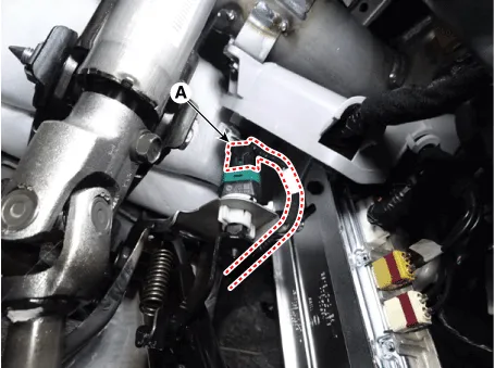
| 3. |
Disconnect the stop lamp switch connector (A).
|
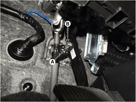
| 4. |
Separate the snap pin (A) and clevis pin (B).
|
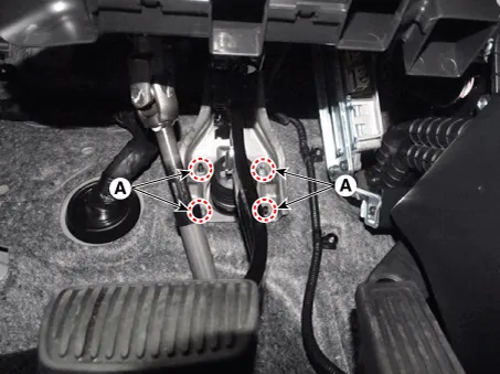
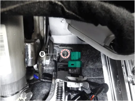
| 5. |
Remove the brake pedal assembly after loosening the mounting bolts (B)
and nuts (A).
|
| Inspection |
| 1. |
Check the brake pedal for bending or twisting.
|
| 2. |
Check the brake pedal return spring for damage.
|
| 3. |
Check the stop lamp switch.
(Refer to Brake System - "Stop Lamp Switch")
|
| Installation |
| 1. |
To install, reverse the removal procedures.
|

Components 1. Brake member assembly 2. Stop lamp switch 3. Brake pedal arm assembly 4. Brake pedal pad
Components 1. Caliper body 2. Caliper carrier 3. Pad inner shim 4. Brake pad 5. Pad retainer
Other information:
Hyundai Santa Fe (TM) 2019-2023 Service and Repair Manual: Rear Glass Defogger
Components and components location Component Location 1. Rear glass defogger relay (Buil-in engine room relay box) 2. Rear glass defogger switch (Dual type) 3. Rear glass defogger switch (Manual type) 4.
Hyundai Santa Fe (TM) 2019-2023 Service and Repair Manual: Electro Chromic Inside Rear View Mirror
Description and operation Description The ECM (Electro Chromatic inside rear view Mirror) is intended dim the reflecting light in the rear view mirror. The forward facing sensor detects brightness of the surroundings, while the rearward looking sensor is for the light from the rear.
Categories
- Manuals Home
- Hyundai Santa Fe Owners Manual
- Hyundai Santa Fe Service Manual
- Emission Control System
- Engine Electrical System
- Tire Pressure Monitoring System (TPMS)
- New on site
- Most important about car
