Hyundai Santa Fe (TM): DC DC converter / Repair procedures
| Removal |
| 1. |
Turn the ignition switch OFF and disconnect the battery (-) terminal.
|
| 2. |
Remove the heater & A/C control unit.
(Refer to Heating, Ventilation and Air Conditioning - "Heater & A/C
Control Unit")
|
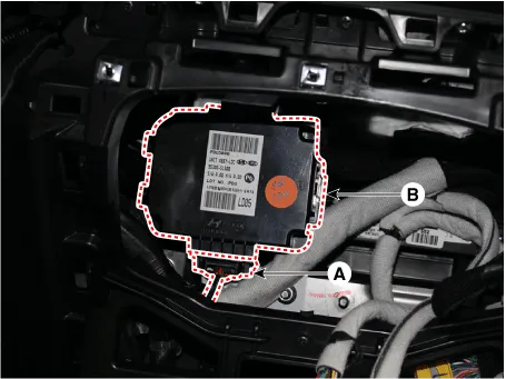
| 3. |
Disconnect the DC/DC converter connector (A).
|
| 4. |
Remove the DC/DC converter (B).
|
| Installation |
|

| 1. |
Install in the reverse order of removal.
|
Circuit Diagram [200W] [450W] Terminal Function [200W] PIn Description 1 Battery power (B+) input 2 Battery power (B+) output 3 IGN1 input 4 ISG signal input 5 ACC input 6 ACC output 7 Ground [450W] PIn Description PIn Description 1 Ground 6 IGN1 input 2 Ground 7 ISG signal input 3 Battery power (B+) output 8 ACC input 4 Battery power (B+) input 9 ACC output 5 Battery power (B+) input [Current Cut Off] 10 Battery power (B+) output [AMP]
Other information:
Hyundai Santa Fe (TM) 2019-2023 Service and Repair Manual: Climate Control Air Filter. Repair procedures
Replacement 1. Remove the glove box. (Refer to Body - "Glove Box") 2. Remove the filter cover (A) by pressing the knob. 3. Replace the air filter (A) with a new one according to the direction of air filter.
Hyundai Santa Fe (TM) 2019-2023 Service and Repair Manual: Description and operation
Description • PDW consists of 8 sensors (front : 4 units, rear : 4 units) that are used to detect obstacles and transmit the result in three separate warning levels, the first, second and third to IBU via LIN communication.
Categories
- Manuals Home
- Hyundai Santa Fe Owners Manual
- Hyundai Santa Fe Service Manual
- Heating,Ventilation And Air Conditioning
- Convenience features
- Instrument cluster
- New on site
- Most important about car
