Hyundai Santa Fe (TM): Body (Interior and Exterior) / Rear Bumper
Components and components location
| Components |

| 1. Rear Bumper
Side Under Cover 2. Rear Bumper Side Bracket |
3. Rear Bumper
Assembly |
Rear Bumper Assembly. Components and components location
| Component Location |
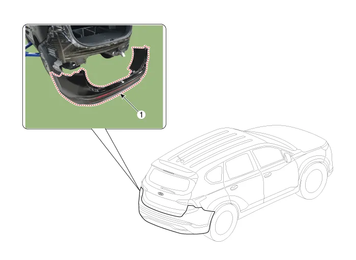
| 1. Rear Bumper
Assembly |
Rear Bumper Assembly. Repair procedures
| Replacement |
|

|

| 1. |
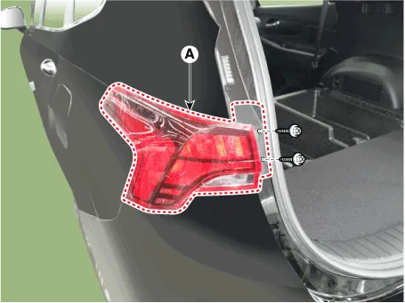
Remove the plug hole, loosen the mounting screws and then remove the
rear combination lamp (A).
|
| 2. |
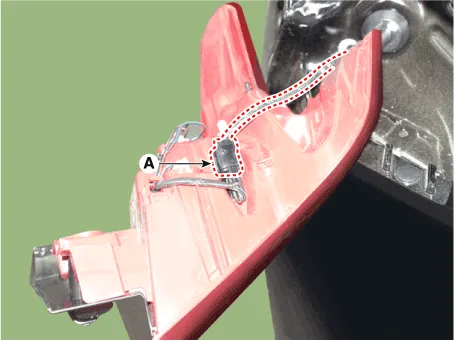
Press the lock pin, separate the rear combination lamp connector (A).
|
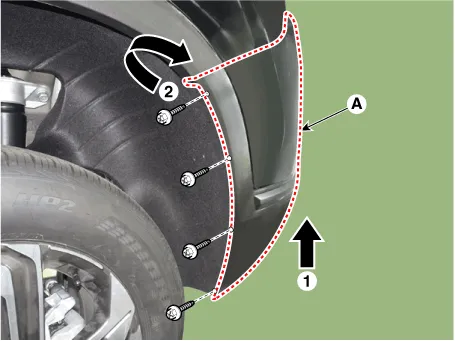
| 3. |
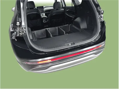
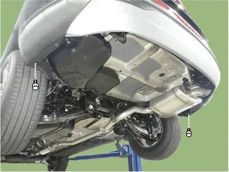
Loosen the rear bumper mounting clips.
[Upper]
[Lower]
|
| 4. |
Loosen the mounting nut and clips, remove the urea tank cover (A).
|
| 5. |
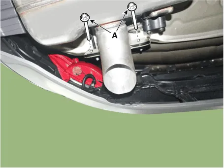
Loosen the mounting nuts, disengage the urea tank (A).
|


| 6. |
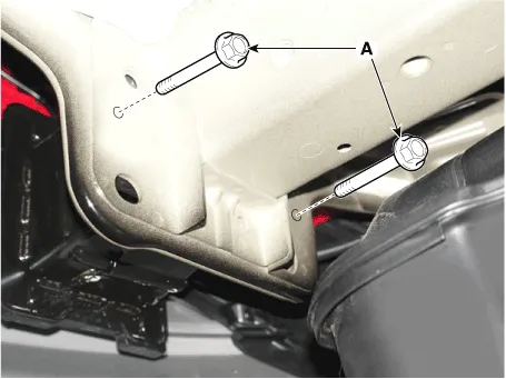
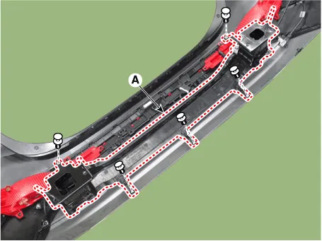
Loosen the rear bumper assembly mounting bolts (A).
[LH]
[RH]
|
| 7. |
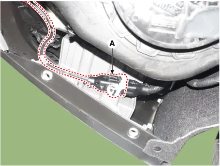
Press the lock pin, separate the rear bumper main connector (A).
|
| 8. |
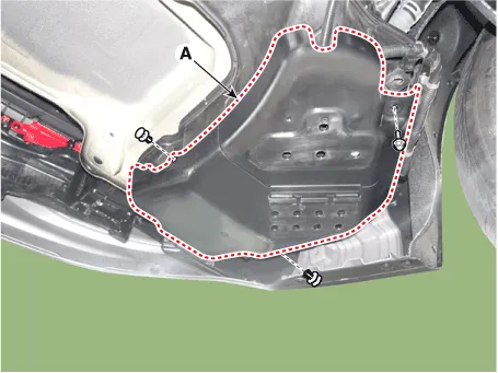
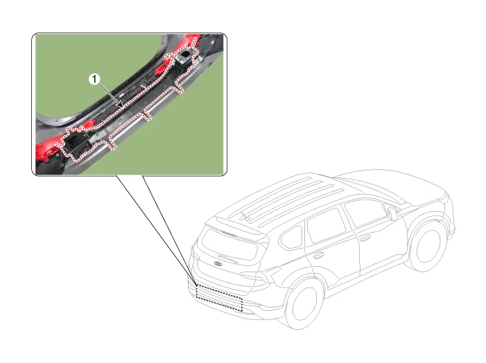
Loosen the mounting screws and retainer on the side of rear bumper (A),
detach the side part of rear bumper.
|
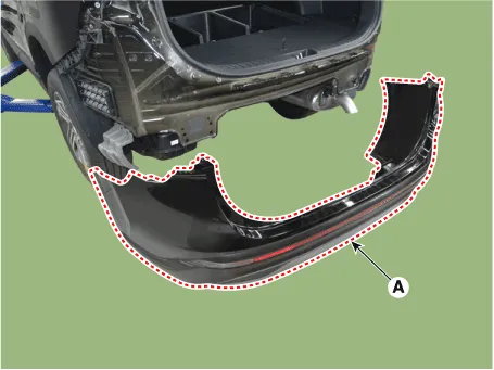
| 9. |
Remove the rear bumper assembly (A).
|
| 10. |
To install, reverse removal procedure.
|

Rear Bumper beam Assembly. Components and components location
| Component Location |
| 1. Rear Bumper
Beam Assembly |
Rear Bumper beam Assembly. Repair procedures
| Replacement |
|
|
| 1. |
Remove the rear bumper assembly.
(Refer to Rear Bumper - "Rear Bumper Assembly")
|
| 2. |
After loosening the mounting clips, remove the rear bumper beam assembly
(A).
|
| 3. |
To install, reverse removal procedure.
|
Components and components location Components 1. Front bumper side bracket [LH] 2. Front bumper side bracket [RH] 3.
Front Seat Assembly. Components and components location Component Location 1. Front seat headrest 2. Front seat back cover 3.
Other information:
Hyundai Santa Fe (TM) 2019-2023 Service and Repair Manual: AC Inverter System
Description and operation Description An inverter is a device that transforms the DC voltage from the battery into an AC voltage (220 V). The inverter can power various electrical devices that consume 200 W or less, including mobile phone or notebook rechargers, audio systems, and TVs.
Hyundai Santa Fe (TM) 2019-2023 Service and Repair Manual: Refrigerant Line. Repair procedures
Replacement [Front suction & Liquid pipe assembly] 1. If a compressor is available, the air conditioner is operated for a few minutes in the engine idle state and then the engine is stopped. 2.
Categories
- Manuals Home
- Hyundai Santa Fe Owners Manual
- Hyundai Santa Fe Service Manual
- Instrument cluster
- Blower
- Rear seats
- New on site
- Most important about car
