Hyundai Santa Fe (TM): Air conditioning System / Refrigerant Line. Repair procedures
| Replacement |
| 1. |
If a compressor is available, the air conditioner is operated for a
few minutes in the engine idle state and then the engine is stopped.
|
| 2. |
Disconnect the negative (-) battery terminal.
|
| 3. |
Recover the refrigerant with a recovery/charging station.
|
| 4. |
Remove the engine cover.
(Refer to Engine Mechanical System - "Engine Cover")
|
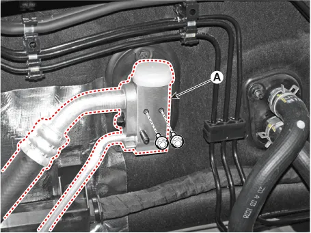
| 5. |
Loosen the mounting bolts and separate the expansion valve (A) fron
evaporator core.
|
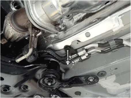
| 6. |
Loosen the mounting nuts and separate the suction line (A), discharge
line (B).
|

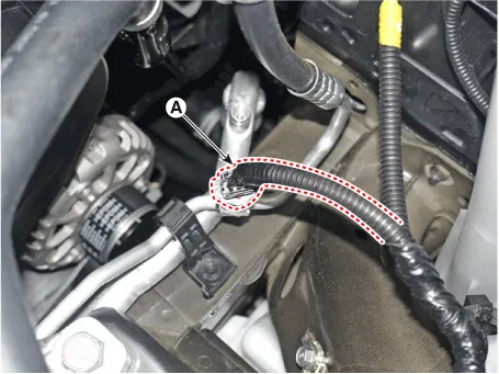
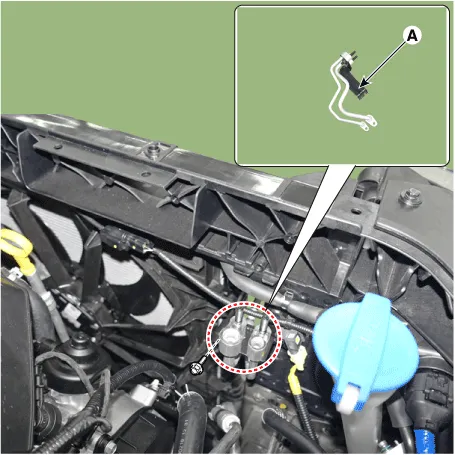
| 7. |
Press the lock pin and separate the APT sensor connector (A).
|
| 8. |
Remove the engine room under cover.
(Refer to Engine Mechanical System - "Engine Room Under Cover")
|
| 9. |
Remove the engine mounting braket.
(Refer to Engine Mechanical System - "Engine Mounting")
|
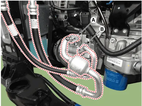
| 10. |
Separate the compressor suction line (A) and discharge line (B) connection
nuts and disconnect the line.
|

| 11. |
Remove the refrigerant pipe line mounting nuts and braket bolt.
|
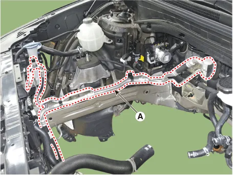
| 12. |
Loosen the mounting bolt and remove the Front suction & Liquid pipe
assembly (A).
|
| 13. |
Install in the reverse order of removal.
|

| 1. |
Remove the front bumper assembly.
(Refer to Body (Interior and Exterior) - "Front Bumper Assembly")
|
| 2. |
Recover the refrigerant with a recovery/charging station.
|
| 3. |
Loosen the mounting nuts and separate the suction line (A), discharge
line (B).
|
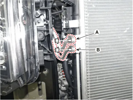
| 4. |
Loosen the mounting nuts, and then disconnect the discharge line (A)
and liquid line (B) from the condenser.
|
| 5. |
Loosen the mounting bolt, remove the refrigerant line (Condenser) (A).
|
| 6. |
Install in the reverse order of removal.
|
| 1. |
If a compressor is available, the air conditioner is operated for a
few minutes in the engine idle state and then the engine is stopped.
|
| 2. |
Disconnect the negative (-) battery terminal.
|
| 3. |
Recover the refrigerant with a recovery/charging station.
|
| 4. |
Remove the rear wheel guard [RH].
(Refer to Body - "Rear Wheel Guard")
|
| 5. |
Loosen the mounting nuts and separate the suction line (A), discharge
line (B).
|

| 6. |
Loosen the mounting bolts , nuts and remove the engine roon under cover[RH].
|

| 7. |
Remove the refrigerant pipe line mounting nuts.
|

| 8. |
Loosen the mounting bolt and remove the Rear suction & Liquid pipe assembly
(A).
|

| 9. |
Install in the reverse order of removal.
|
Components 1. Front Suction & Liquid Pipe Assembly 2. Rear Suction & Liquid Pipe Assembly
Description The compressor is the power unit of the A/C system. It is located on the side of engine block and driven by a V-belt of the engine.
Other information:
Hyundai Santa Fe (TM) 2019-2023 Service and Repair Manual: Rear Occupant Alert
Description and operation Description The system detects the passenger in the vehicle and prevents the driver from getting off the vehicle with the passenger in the back. - 1st warning: If you open the driver's door after you open and then close the rear passenger and turn the engine off, the system provides warn
Hyundai Santa Fe (TM) 2019-2023 Service and Repair Manual: Receiver-Drier. Repair procedures
Replacement 1. Using a Lwrench, remove the cap (A) on the bottom of the receiver-drier. 2. Remove the receiver-drier (A) from condenser using a long nose plier. Check for crumbled receiver-drier and clogged bottom cap filter.
Categories
- Manuals Home
- Hyundai Santa Fe Owners Manual
- Hyundai Santa Fe Service Manual
- Rear seats
- Blower
- 4 Wheel Drive (4WD) System
- New on site
- Most important about car
