
Hyundai Santa Fe (TM): Body (Interior and Exterior) / Mirror
Outside Rear View Mirror. Components and components location
| Component Location |
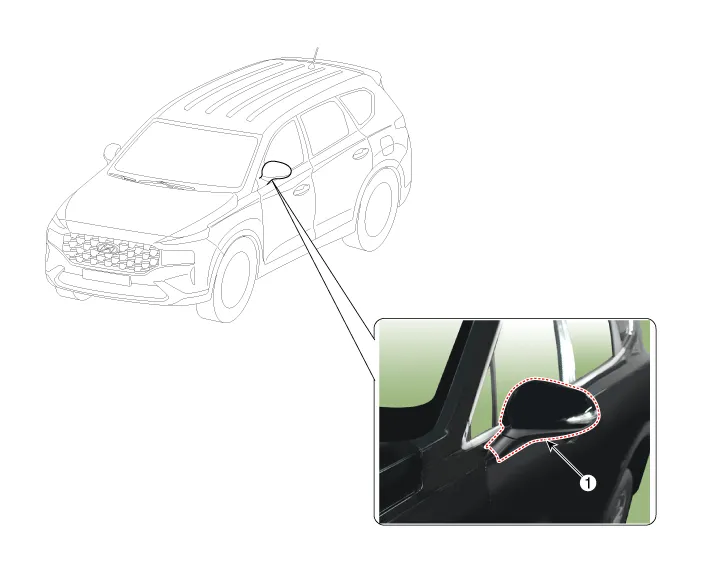
| 1. Outside Rear
View Mirror |
Outside Rear View Mirror. Repair procedures
| Replacement |
|

|

| 1. |
Remove the front door trim.
(Refer to Front door - "Front Door Trim")
|
| 2. |
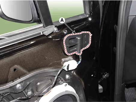
Using a screwdriver or remover, remove the outside rear view mirror
inner cover (A).
|
| 3. |
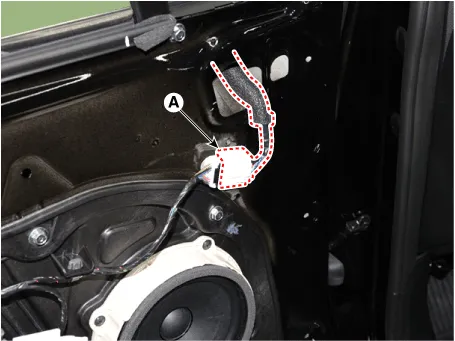
Press the lock pin, separate the outside rear view mirror connector
(A).
|
| 4. |
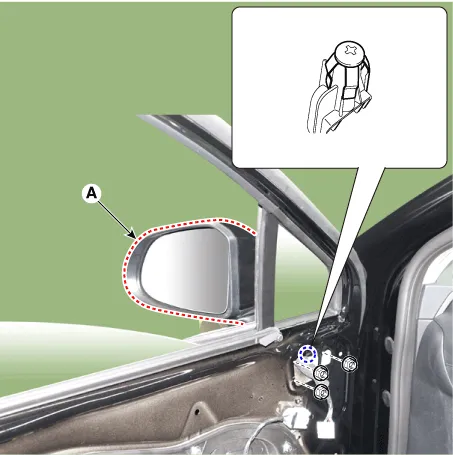
Loosen the mounting nuts and clip, remove the outside rear view mirror
(A).
|
| 5. |
To install, reverse removal procedure.
|

Inside Rear View Mirror. Components and components location
| Component Location |
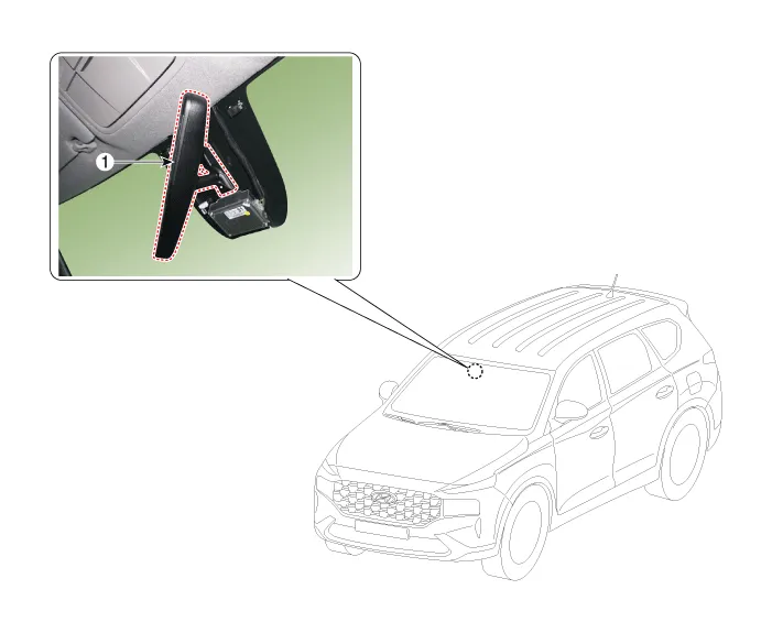
| 1. Inside Rear
View Mirror |
Inside Rear View Mirror. Repair procedures
| Replacement |
|
| 1. |
Remove the ECM mirror cover (A).
|
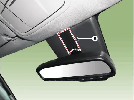
| 2. |
Remove the rain sensor cover (A).
|

| 3. |
Disconnect the ECM mirror connector (A).
|

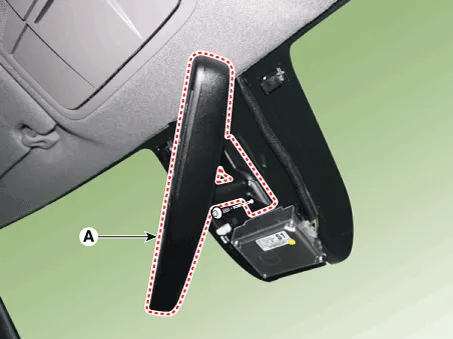
| 4. |
Loosen the mounted screws and push the ECM mirror base upward to remove
the ECM mirror assembly (A).
|
| 5. |
To install, reverse removal procedure.
|
|
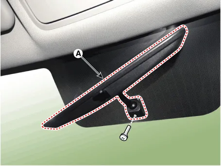
| 1. |
Loosen the mounting screw and remove the inside rear view mirror assembly
(A).
|
| 2. |
To install, reverse the removal procedure.
|
Components and components location Component 1. Mechanism rail assembly 2. Center cover assembly 3. Roller blind motor 4.
Components and components location Component Location 1. Cowl Top Cover Repair procedures Replacement 1.
Other information:
Hyundai Santa Fe (TM) 2019-2023 Service and Repair Manual: Refrigerant Line. Repair procedures
Replacement [Front suction & Liquid pipe assembly] 1. If a compressor is available, the air conditioner is operated for a few minutes in the engine idle state and then the engine is stopped. 2.
Hyundai Santa Fe (TM) 2019-2023 Service and Repair Manual: Parking Distance Warning (PDW)
Description and operation Description • PDW consists of 8 sensors (front : 4 units, rear : 4 units) that are used to detect obstacles and transmit the result in three separate warning levels, the first, second and third to IBU via LIN communication.
Categories
- Manuals Home
- Hyundai Santa Fe Owners Manual
- Hyundai Santa Fe Service Manual
- Fuel Delivery System
- Horn
- LCD Display
- New on site
- Most important about car
