Hyundai Santa Fe (TM): Body (Interior and Exterior) / Crash Pad
Components and components location
| Components (1) |
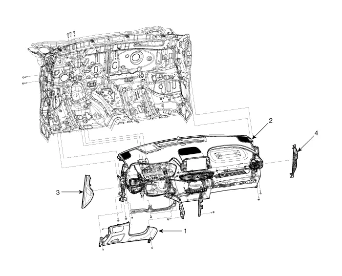
| 1. Crash pad
lower panel 2. Crash pad assembly |
3. Crash pad
side cover [LH] 4. Crash pad side cover [RH] |
| Componets (2) |
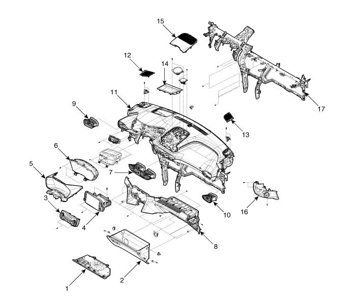
| 1. Crash pad
under cover [RH] 2. Glove box 3. Heater & A/C controller 4. A.V.N Head unit 5. Cluster fascia panel 6. Cluster assembly 7. Center airvent duct assembly 8. Crash pad center panel 9. Side airvent duct assembly [LH] |
10. Side airvent
duct assembly [RH] 11. Main crash pad 12. Side speaker grill assembly [LH] 13. Side speaker grill assembly [RH] 14. Head up display cover 15. Center speaker grill assembly 16. Steering column lower shroud 17. Cowl cross bar assembly |
Cluster Fascia Panel. Components and components location
| Component Location |
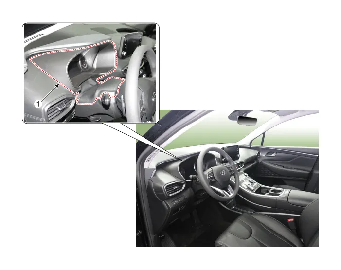
| 1. Cluster Fascia
Panel |
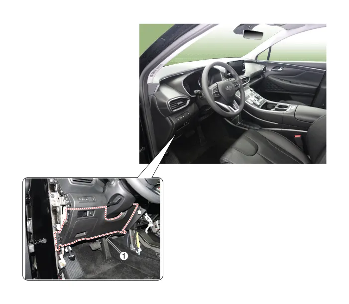
Cluster Fascia Panel. Repair procedures
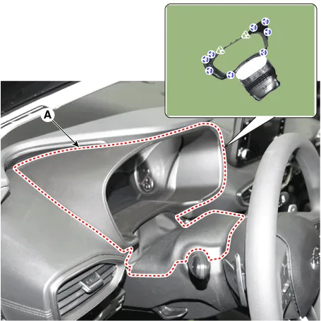
| Replacement |
|

|

| 1. |
Using a screwdriver or remover, remove the cluster fascia panel (A).
|
| 2. |
To install, reverse the removal procedure.
|
Crash Pad Under Cover. Repair procedures
| Replacement |
|
|

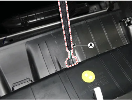
| 1. |
Press the lock pin (B) and then remove the crash pad under cover (A).
|
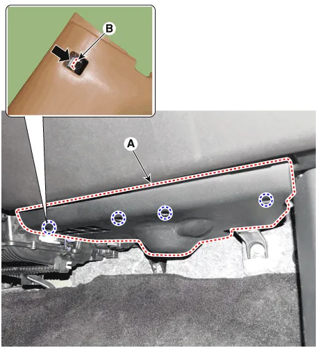
| 2. |
To install, reverse removal procedure.
|
Crash Pad Lower Panel. Components and components location
| Component Location |
| 1. Crash Pad
Lower Panel |
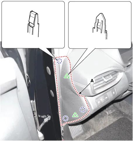
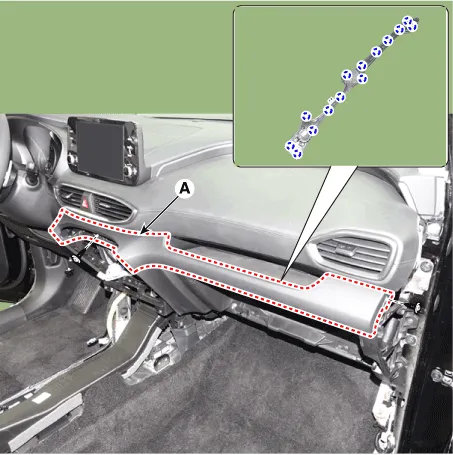
Crash Pad Lower Panel. Repair procedures
| Replacement |
|
|
| 1. |
Using a screwdriver or remover, remove the crash pad side cover [LH]
(A).
|
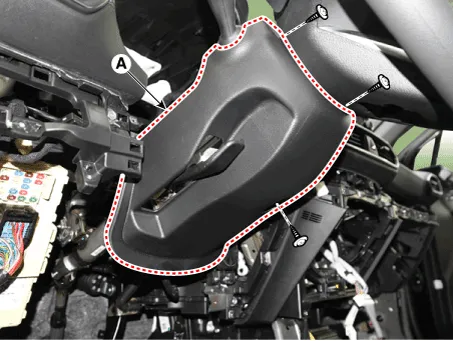
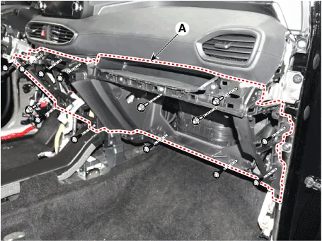
| 2. |
Loosen the mounting screws and remove the crash pad lower panel (A).
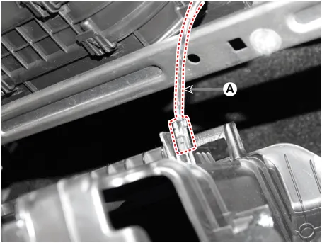
|
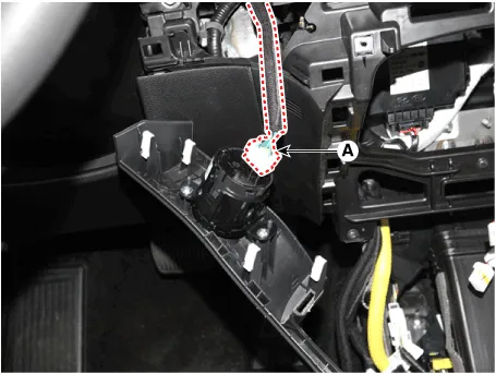
| 3. |
Disconnect the crash pad lower switch connectors (A).
|
| 4. |
To install, reverse removal procedure.
|
Steering Column Shroud Panel. Components and components location
| Component Location |
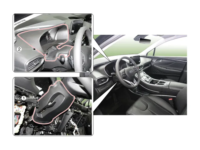
| 1. Steering Column
Shroud Lower Panel |
2. Steering Column
Shroud Upper Panel |
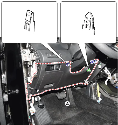
Steering Column Shroud Panel. Repair procedures
| Replacement |
[Steering column shroud upper panel]
|
|
| 1. |
Using a screwdriver or remover, remove the steering column shroud panel
(A).
|
| 2. |
To install, reverse removal procedure.
|
[Steering column shroud lower panel]
|
|
| 1. |
Remove the steering column shroud panel.
|
| 2. |
Remove the crash pad lower panel.
(Refer to Crash Pad - "Crash Pad Lower Panel")
|
| 3. |
Loosen the mounting screws by turning the steering wheel to the left
and right, and remove the steering column shroud lower panel (A).
|
| 4. |
To install, reverse removal procedure.
|
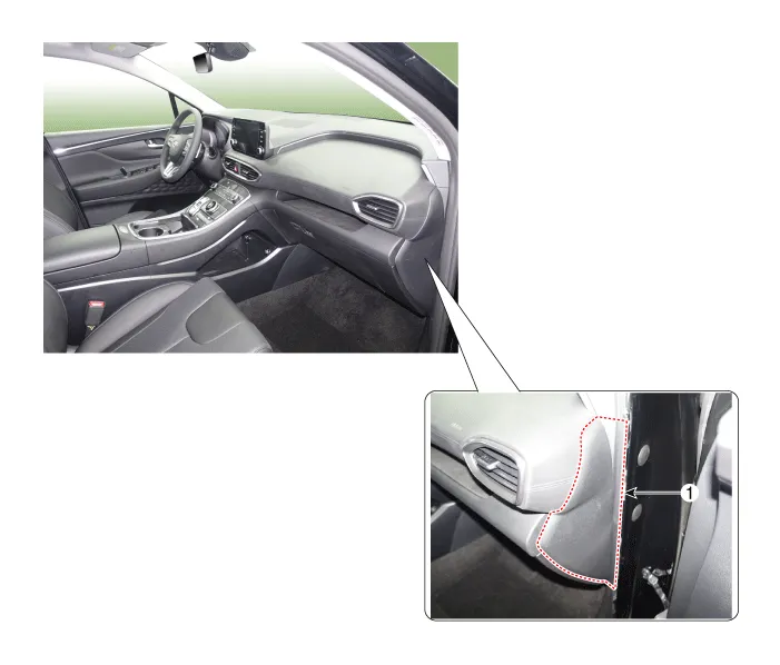
Crash Pad Side Cover. Components and components location
| Component Location |
| [LH] |
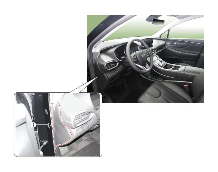
| 1. Crash pad
side cover [LH] |
| [RH] |
| 1. Crash pad
side cover [RH] |
Crash Pad Side Cover. Repair procedures
| Replacement |
|
|
| 1. |
Using a screwdriver or remover, remove the crash pad side cover (A).
[LH]
[RH]
|
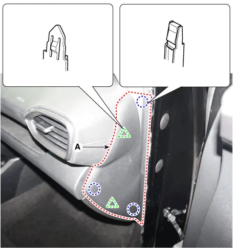
| 2. |
To install, reverse removal procedure.
|
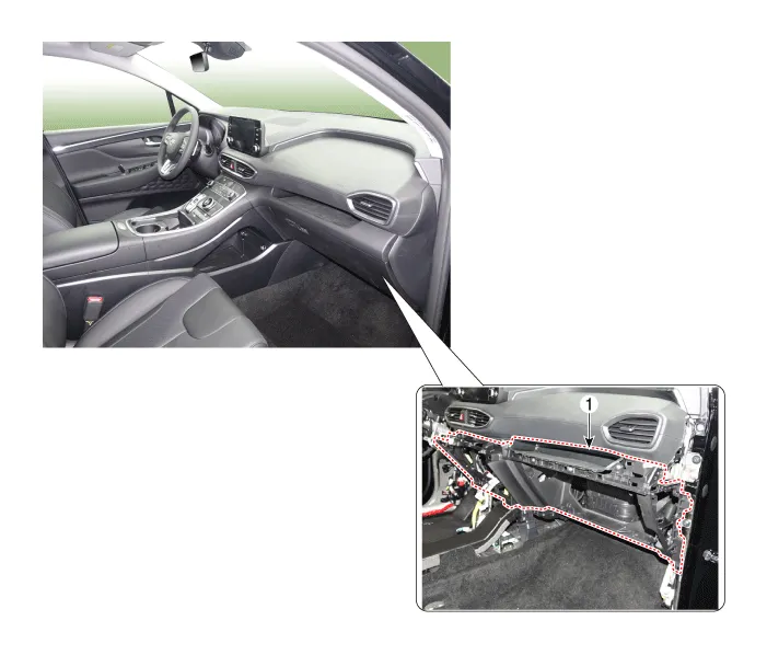
Glove Box. Components and components location
| Component Location |
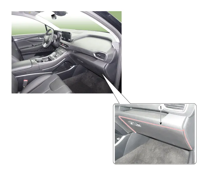
| 1. Glove Box
|
Glove Box. Repair procedures
| Replacement |
|
|
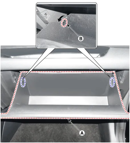
| 1. |
Open the glove box (A).
|
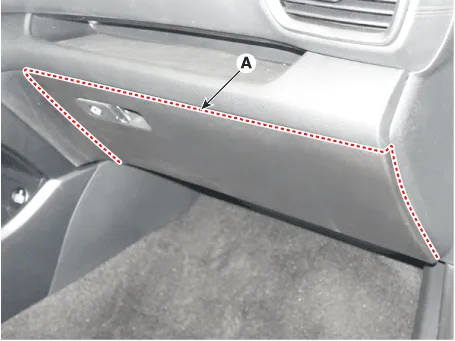
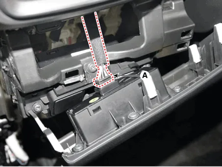
| 2. |
Pull out the both sides stopper (B) from the glove box (A).
|
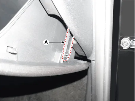
| 3. |
Remove the air damper (A) from the glove box.
|
| 4. |
Remove the lock pins (A) and then remove the glove box.
|
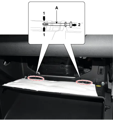
| 5. |
To install, reverse removal procedure.
|
Crash Pad Center Panel. Components and components location
| Component Location |
| 1. Crash pad
center panel |
Crash Pad Center Panel. Repair procedures
| Replacement |
|
|
| 1. |
Remove the floor console assembly.
(Refer to Floor Console - "Floor Console Assembly")
|
| 2. |
Remove the crash pad under cover.
(Refer to Crash Pad - "Crash Pad Under Cover")
|
| 3. |
Remove the glove box.
(Refer to Crash Pad - "Glove Box")
|
| 4. |
Remove the crash pad lower panel.
(Refer to Crash Pad Lower Panel")
|
| 5. |
Remove the cowl side trim.
(Refer to Interior Trim - "Cowl Side Trim")
|
| 6. |
Remove the crash pad side cover [RH] (A).
|
| 7. |
Remove the crash pad garnish (A).
|
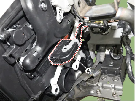
| 8. |
Press the lock pin, separate the start button connector (A).
|
| 9. |
Loosen the mounting screws and bolts, remove the crash pad center panel
(A).
|
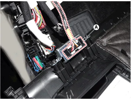
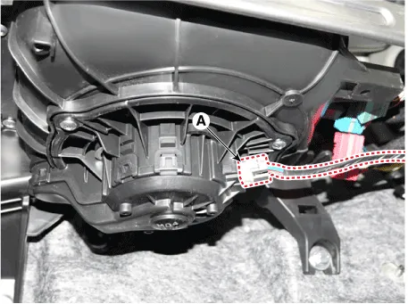
| 10. |
Press the lock pin, separate the connectors (A).
|
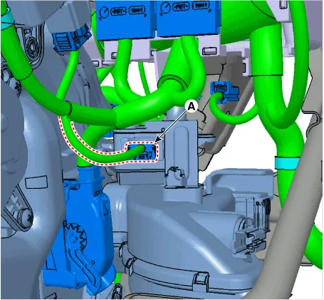
| 11. |
Press the lock pin, separate the in-car sensor connector (A) and hoses
(B).
|
| 12. |
To install, reverse removal procedure.
|
Main Crash Pad Assembly. Components and components location
| Component Location |
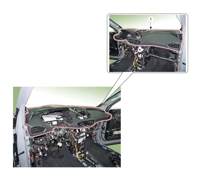
| 1. Main crash
pad assembly |
Main Crash Pad Assembly. Repair procedures
| Replacement |
|
|
| 1. |
Disconnect the negative (-) battery terminal.
|
| 2. |
Remove the front pillar trim.
(Refer to Interior Trim - "Front Pillar Trim")
|
| 3. |
Remove the floor console assembly.
(Refer to Floor Console - "Floor Console Assembly")
|
| 4. |
Remove the crash pad lower panel.
(Refer to Crash Pad - "Crash Pad Lower Panel")
|
| 5. |
Remove the cluster fascia panel.
(Refer to Cluster Pad - "Center Fascia Panel")
|
| 6. |
Remove the audio and AVN head unit.
(Refer to Body Electrical System - "Audio Unit")
|
| 7. |
Remove the crash pad center panel.
(Refer to Crash Pad - "Crash Pad Center Panel")
|
| 8. |
Remove the steering wheel.
(Refer to Steering System - "Steering Wheel")
|
| 9. |
Remove the steering column shroud lower panel.
(Refer to Crash Pad - "Steering Column Shroud Panel")
|
| 10. |
Remove the multifunction switch assembly.
(Refer to Body Electrical System - "Multifunction Switch")
|
| 11. |
Remove the instrument cluster.
(Refer to Body Electrical System - "Instrument Cluster")
|
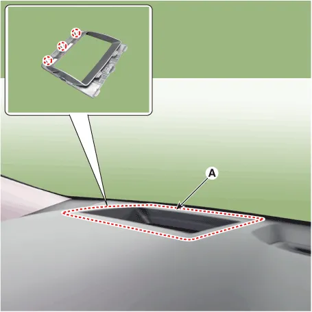
| 12. |
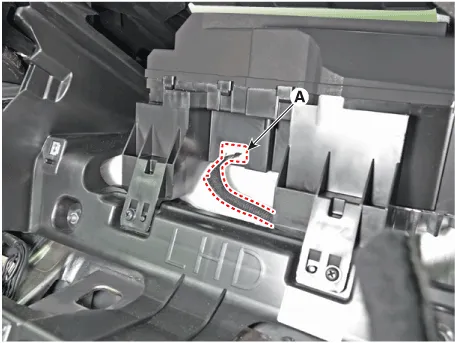
Remove the head up display (HUD) upper cover (A).
|
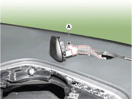
| 13. |
Press the lock pin, separate the HUD unit connector (A).
|
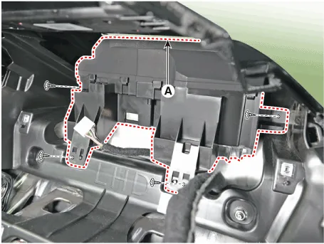
| 14. |
Loosen the mounting screws, remove the HUD unit assembly (A).
|
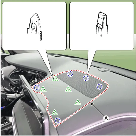
| 15. |
Remove the crash pad upper garnish (A).
|
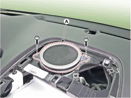
| 16. |
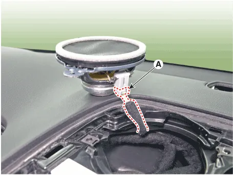
Loosen the mounting screws, remove the center speaker (A).
|
| 17. |
Press the lock pin, separate the center speaker connector (A).
|
| 18. |
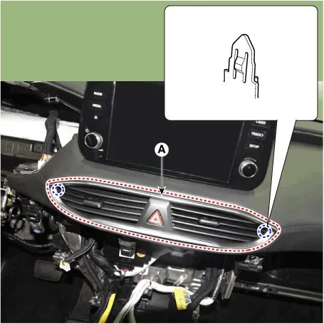
Remove the crash pad air vent (A).
|
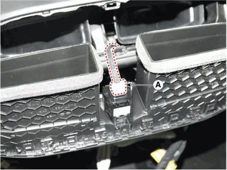
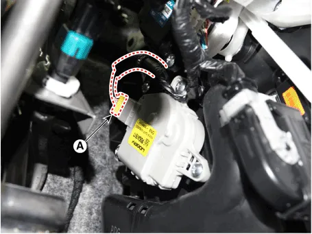
| 19. |
Press the lock pin, separate the connector (A).
|
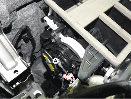
| 20. |
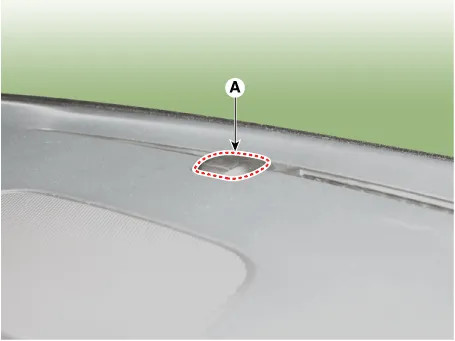
Remove the photo sensor (A).
|
| 21. |
Press the lock pin, separate the photo sensor connector (A).
|
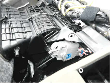
| 22. |
Loosen the mounting screw, remove the crash pad garnish [LH] (A).
|
| 23. |
Press the lock pin, separate the connector (A).
|
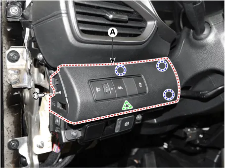
| 24. |
Loosen the mounting screws, remove the EPB switch assembly (A).
|
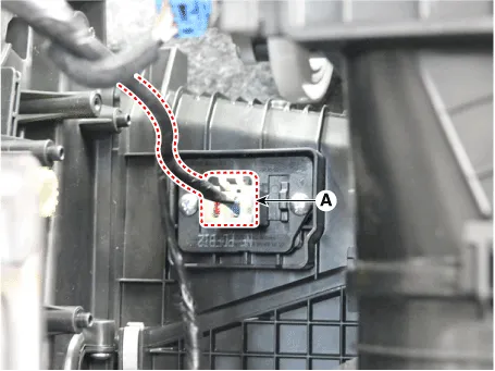
| 25. |
Press the lock pin, separate the EPS switch connector (A).
|
| 26. |
Loosn the passenger's airbag(PAB) mounting bolts (A).
|
| 27. |
Loosen the mounting bolts and nuts and remove the main crash pad assembly
(A).
|

| 28. |
Press the lock pin, separate the passenger's airbag(PAB) connectors
(A).
|
| 29. |
Press the lock pin, separate the side speaker connector (A).
[LH]
[RH]
|
| 30. |
To install, reverse removal procedure.
|
Cowl Cross Bar Assembly. Components and components location
| Component Location |

| 1. Cowl cross
bar assembly |
Cowl Cross Bar Assembly. Repair procedures
| Replacement |
|
|
| 1. |
Disconnect the negative (-) battery terminal.
|
| 2. |
Recover the refrigerant with a recovery/recycling/charging station.
|
| 3. |
When the engine is cool, drain the engine coolant from the radiator.
(Refer to Engine Mechanical System - “Coolant”)
|
| 4. |
Remove the cowl top cover.
(Refer to "Cowl Top Cover")
|
| 5. |
Disconnect the inlet and outlet heater hoses from the heater unit.
(Refer to Heating,Ventilation And Air Conditioning - "Heater Unit")
|
| 6. |
Remove both sides of front seat assembly.
(Refer to Front Seat - "Front Seat Assembly")
|
| 7. |
Remove the main crash pad assembly.
(Refer to Crash Pad - "Main Crash Pad Assembly")
|
| 8. |
Disconnect the steering column connectors.
(Refer to Steering System - "Steering Column and Shaft")
|
| 9. |
Loosen the mounting nuts and through bolts in the frontal area and lower
the steering column.
(Refer to Steering System - "Steering Column and Shaft")
|
| 10. |
Loosen the engine room cowl cross bar assembly mounting bolts.
|
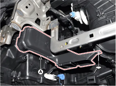
| 11. |
Loosen the mounting nuts and remove the floor air duct (A).
|
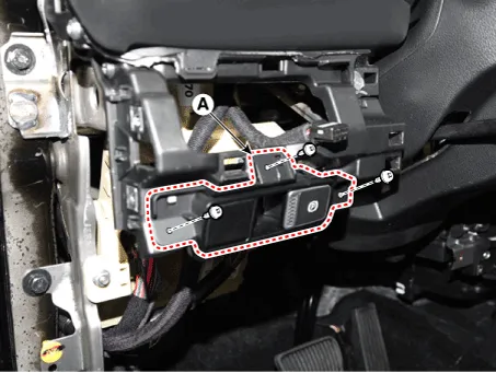
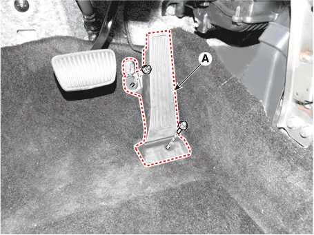
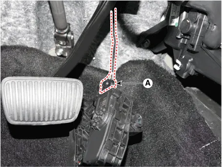
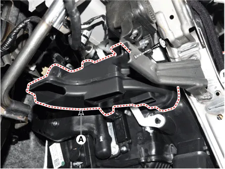
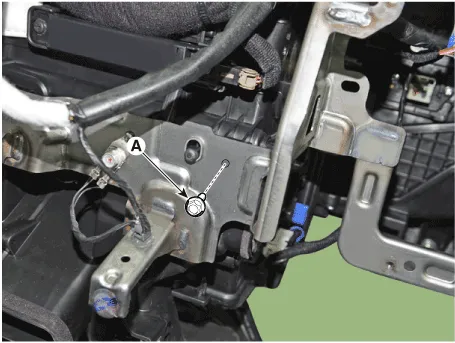
| 12. |
Loosen the mounting bolt and nut, remove the accelerator pedal module
(A).
|
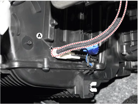
| 13. |
Press the lock pin, separate the accelator pedal connector (A).
|
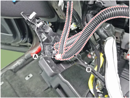
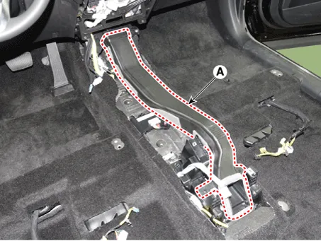
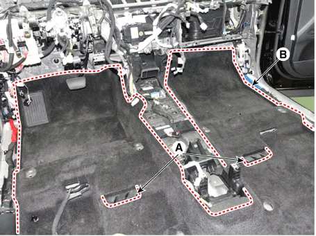
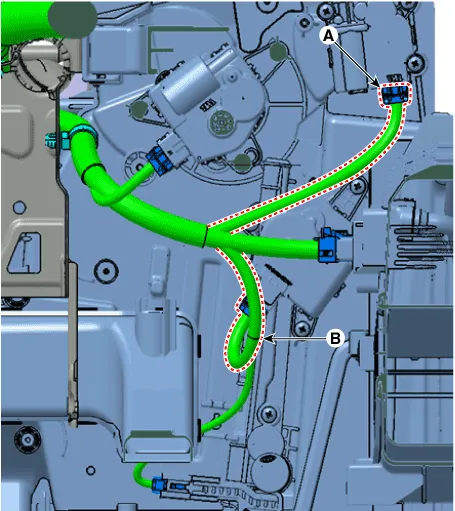
| 14. |
Remove the rear air duct (A) and then separate the floor carpet (B)
backwards.
|
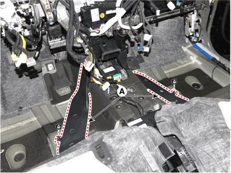
| 15. |
Loosen the mounting nuts and remove the rear heating duct (A).
|
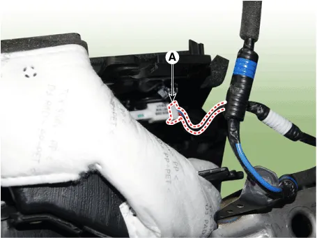
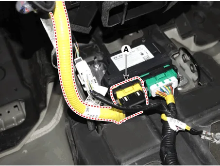
| 16. |
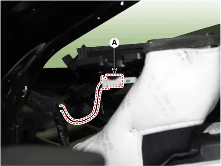
Press the lock pin and separate the airbag control module(SRSCM) connector
(A).
|
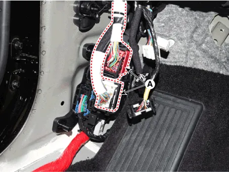
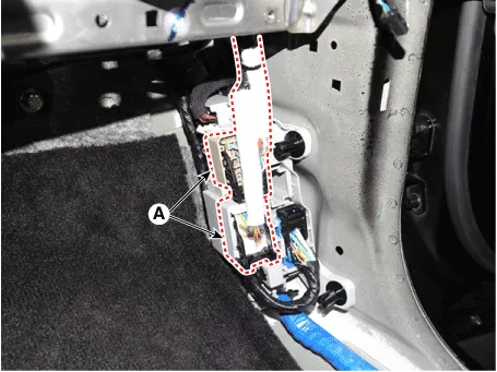
| 17. |
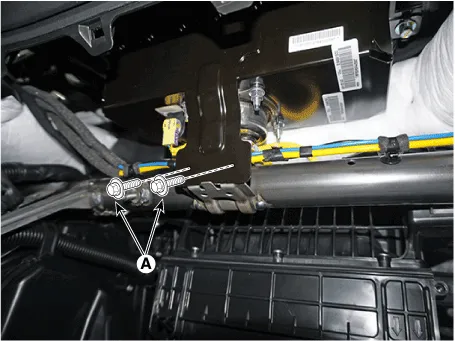
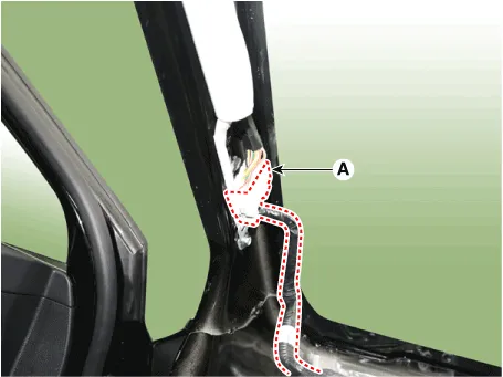
Disconnect the connector (A) and the mounting wiring fasteners in the
front pillar.
[Driver's]
[Passenger's]
|
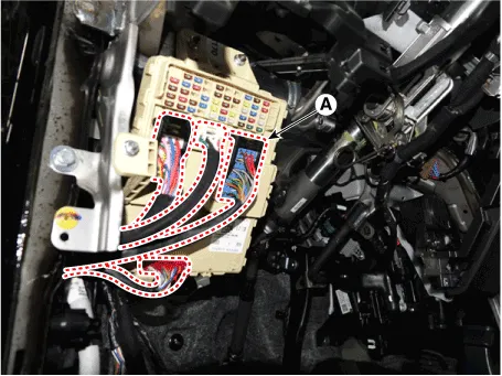
| 18. |
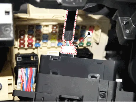
Disconnect the passenger compartment junction box connectors (A).
|
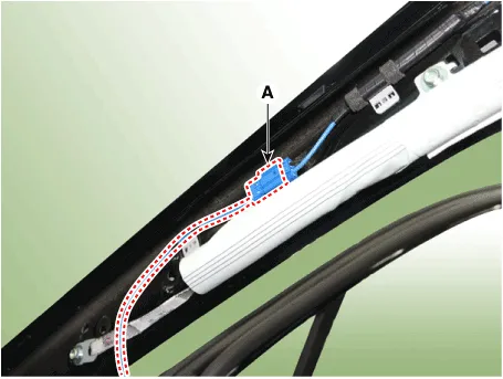
| 19. |
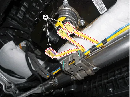
Disconnect the multi box connectors (A).
[Driver's]
[Passenger's]
|
| 20. |
Disconnect the heater and blower unit connector.
|
| 21. |
Loosen the heater & blower unit front mounting bolt (A).
|
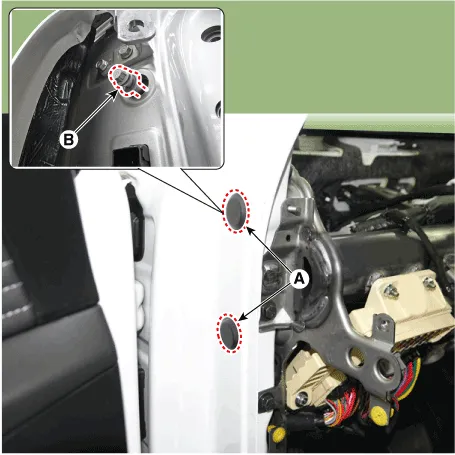
| 22. |
Loosening the cowl cross bar side mounting bolt (B) after loosening
the plug hole (A).
|
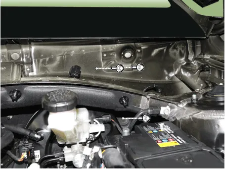
| 23. |
Loosen the mounting bolts and remove the cowl croos bar assembly (A).
|

| 24. |
To install, reverse removal procedure.
|
Components and components location Components 1. Floor console side cover 2. Floor console upper cover 3. Console armrest lock assembly 4.
Components and components location Components [General Type] 1. Sunvisor 2. Roof trim Components [Panorama Sunroof Type] 1.
Categories
- Manuals Home
- Hyundai Santa Fe Owners Manual
- Hyundai Santa Fe Service Manual
- Emission Control System
- Engine Mechanical System
- Engine Control/Fuel System
- New on site
- Most important about car

Copyright © 2026 www.hsafe4.com - 0.0268