Hyundai Santa Fe (TM): Body (Interior and Exterior) / Roof Trim
Components and components location
| Components |
| [General Type] |
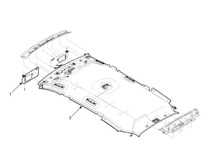
| 1. Sunvisor |
2. Roof trim |
| Components |
| [Panorama Sunroof Type] |
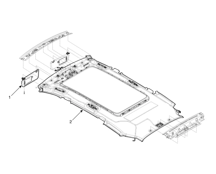
| 1. Sunvisor |
2. Roof trim |
Sunvisor. Components and components location
| Component Location |
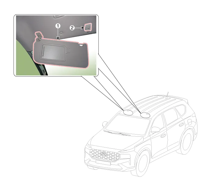
| 1. Sunvisor |
2. Retainer |
Sunvisor. Repair procedures
| Replacement |
|

|

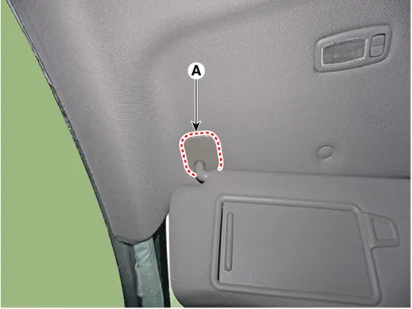
| 1. |
Remove the sunvisor pivot cover (A).
|
| 2. |
Loosen the mounting screw and seperate the sunvisor (A).
|
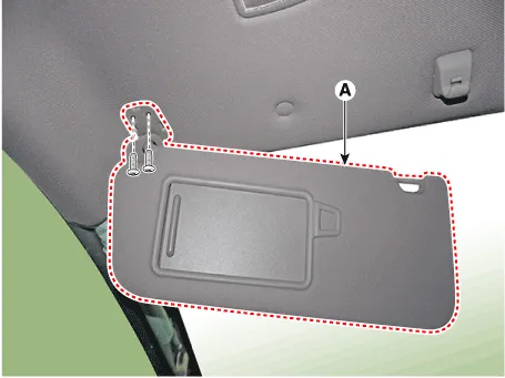
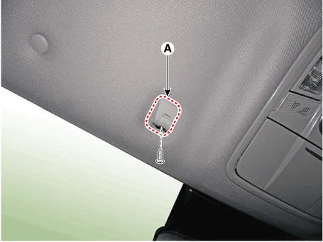
| 3. |
Loosen the mounting screws and remove the retainer (A).
|
| 4. |
To install, reverse removal procedure.
|

Assist Handle. Components and components location
| Component Location |
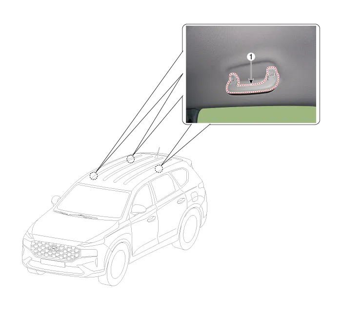
| 1. Assist Handle |
Assist Handle. Repair procedures
| Replacement |
|
|
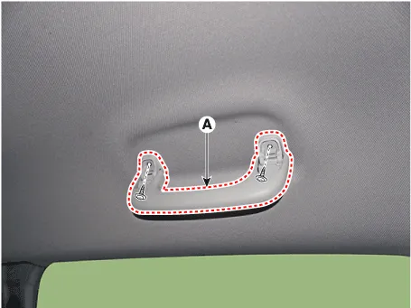
| 1. |
After lifting up the assist handle caps and loosening the mounting screws,
remove the assist handle (A).
|
| 2. |
To install, reverse removal procedure.
|
Roof Trim Assembly. Components and components location
| Component Location |
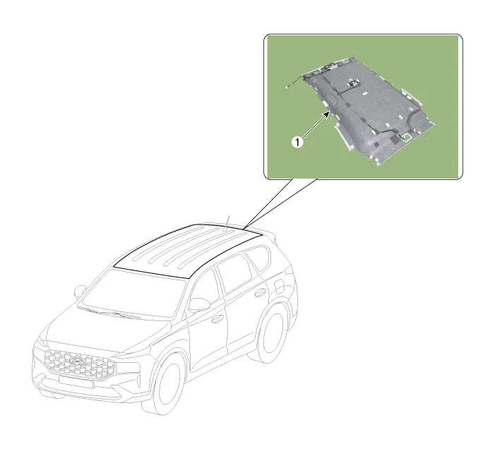
| 1. Roof Trim
Assembly |
Roof Trim Assembly. Repair procedures
| Replacement |
|
|
| 1. |
Remove the front seat.
(Refer to Front Seat - "Front Seat Assembly")
|
| 2. |
Remove the rear seat.
(Refer to Rear Seat - "Rear Seat Assembly")
|
| 3. |
Remove the front pillar trim.
(Rear to Interior Trim - "Front Pillar Trim")
|
| 4. |
Remove the center pillar upper trim.
(Rear to Interior Trim - "Center Pillar Trim")
|
| 5. |
Remove the rear pillar trim.
(Rear to Interior Trim - "Rear Pillar Trim")
|
| 6. |
Remove the sunvisor and retainer.
(Rear to Roof Trim - "Sunvisor")
|
| 7. |
Remove the assist handle.
(Rear to Roof Trim - "Assist Handle")
|
| 8. |
Remove the overhead console lamp.
(Rear to Body Electrical System - "Overhead Console Lamp")
|
| 9. |
Remove the room lamp.
(Rear to Body Electrical System - "Room Lamp")
|
| 10. |
Remove the ECM mirror connector.
(Refer to Body Electrical System - "Electro Chromic Inside Rear View
Mirror")
|
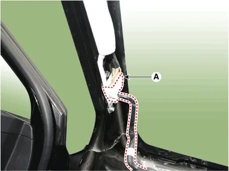
| 11. |
Separate the roof trim main connector (A) from the front pillar section.
[LH]
[RH]
|
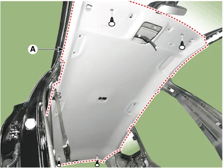
| 12. |
Remove the roof trim mounting clip and remove the roof trim assembly
(A).
|
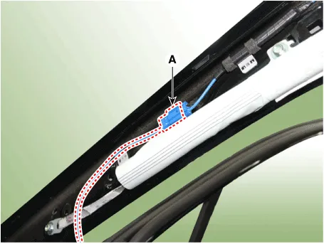
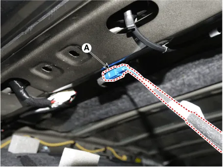
| 13. |
Press the lock pin, separate the roof trim connector (A).
|
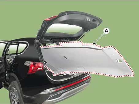
| 14. |
Remove the roof trim assembly (A) from the vehicle through the tailgate.
|
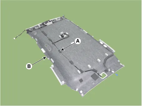
| 15. |
Remove roof trim wiring harness (A) from the roof trim (B).
|
| 16. |
To install, reverse removal procedure.
|
Components and components location Components (1) 1. Crash pad lower panel 2. Crash pad assembly 3. Crash pad side cover [LH] 4.
Components and components location Components 1. Front pillar trim 2. Cowl side trim 3. Center pillar upper trim 4.
Other information:
Hyundai Santa Fe (TM) 2019-2023 Service and Repair Manual: Button Engine Start System
Description and operation Description System Overview The System offers the following features: – Changing the state of engine ignition and power by using the start button. – Controlling external relays for ACC / IGN1 / IGN2 terminal switching and STARTER, without use
Hyundai Santa Fe (TM) 2019-2023 Service and Repair Manual: In-car Sensor. Description and operation
Description The In-car air temperature sensor is built in the heater & A/C control unit. The sensor consists of a thermistor that measures the inside temperature. The signal decided by the resistance value that changes in accordance with perceived inside temperature, is delivered to heater control unit, and according t
Categories
- Manuals Home
- Hyundai Santa Fe Owners Manual
- Hyundai Santa Fe Service Manual
- Restraint
- Front Radar Unit. Repair procedures
- Battery. Specifications
- New on site
- Most important about car
