Hyundai Santa Fe (TM): Body Electrical System / Auto Lighting Control System
Description and operation
| Description |
| 1. |
Do not add another device on top of this device.
|
| 2. |
Be sure to switch to manual during poor visibility climate, such as
fog, heavy rain, or cloudy weather.
|
| 3. |
Illumination intensity in an actual vehicle is not always constant,
and lamp ON/OFF time may very depending on the climate, season, and
surrounding environment.
|
| 4. |
Use this system only during sunrise and sunset period, and manually
control lamp ON/OFF for general conditions.
|
| 5. |
Error may occur if light block coating that may change interior illumination
is applied.
|
Components and components location
| Component Location |
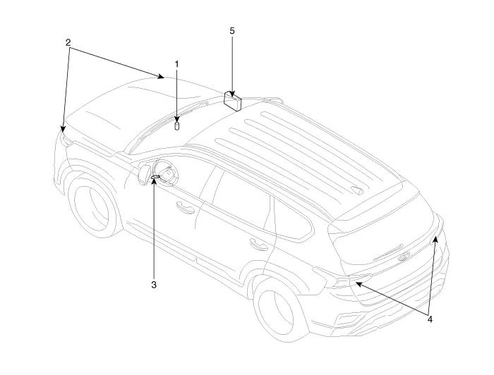
| 1. Auto light
sensor 2. Head lamps 3. Lighting switch (Auto) |
4. Tail lamps 5. IBU (Integrated Body Control Unit) |
Specifications
| Specifications |
|
Items |
Specifications |
|
|
Rated voltage |
5V |
|
|
Load |
Max. 1mA (When head lamp lighting) |
|
|
Illuminations (LUX) |
50 |
1.22 ± 0.27V |
|
150 |
3.23 ± 0.71V |
|
Schematic diagrams
| Circuit Diagram |
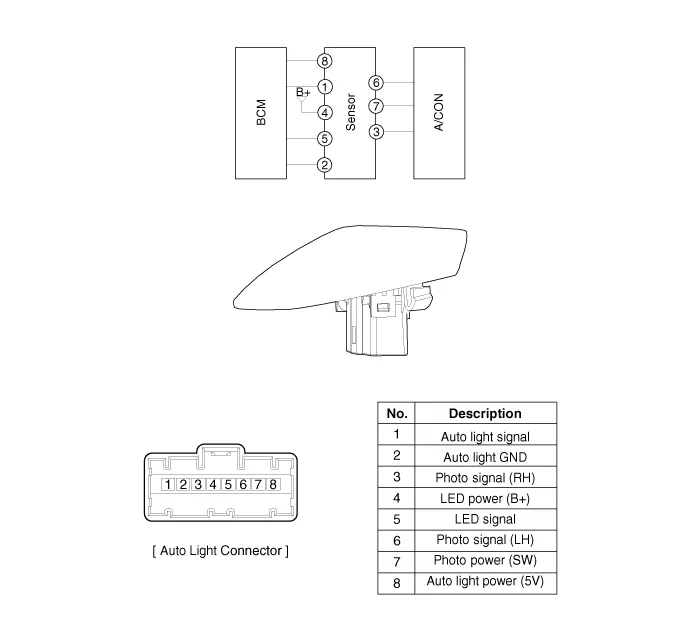
Auto Light Sensor. Repair procedures
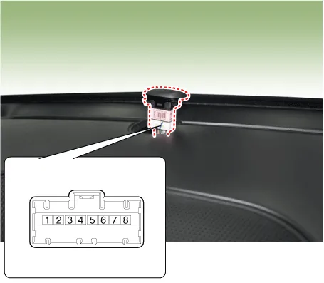
| Inspection |
|

| Removal |
| 1. |
Disconnect the negative (-) battery terminal.
|
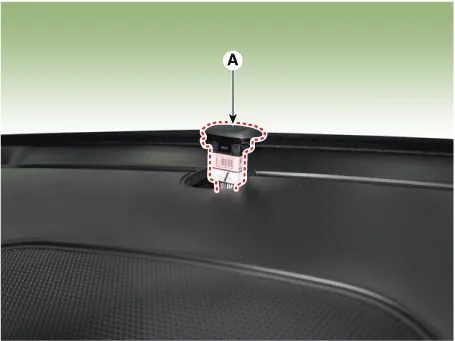
| 2. |
Remove the photo & auto light sensor (A) from crash pad upper side by
using a flat-tip screwdriver.
|
| 3. |
Remove the auto light connector.
|
| Installation |
| 1. |
Reconnect the auto light connector.
|
| 2. |
Install the auto light sensor.
|
Components and components location Component Location 1. Head lamp (Low) 2. Head lamp (High) 3. Daytime running light (DRL)/Positioning lamp 4.
Components and components location Component Location 1. Head lamp leveling actuator Head Lamp Leveling Switch.
Other information:
Hyundai Santa Fe (TM) 2019-2023 Service and Repair Manual: AC Inverter System
Description and operation Description An inverter is a device that transforms the DC voltage from the battery into an AC voltage (220 V). The inverter can power various electrical devices that consume 200 W or less, including mobile phone or notebook rechargers, audio systems, and TVs.
Hyundai Santa Fe (TM) 2019-2023 Service and Repair Manual: Rear View Monitor (RVM)
Description and operation Description Back view camera will activate when the backup light is ON with the ignition switch ON and the shift lever in the R position. This system is a supplemental system that shows behind the vehicle through the H/UNIT or the ECM (Reverse Display Room Mirror) mirror while backing-up.
Categories
- Manuals Home
- Hyundai Santa Fe Owners Manual
- Hyundai Santa Fe Service Manual
- Rear seats
- 4 Wheel Drive (4WD) System
- Gauges and meters
- New on site
- Most important about car
