Hyundai Santa Fe (TM): Brake System / Stop Lamp Switch. Schematic diagrams
| Schematic Diagram |
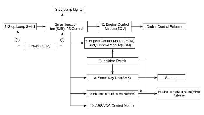
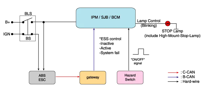
| System circuit diagram |
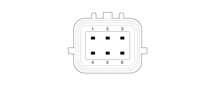
| Terminal Function |
|
Teminal |
Description |
|
1 |
IGN1 |
|
2 |
Engine Control Module (ECM) |
|
3 |
- |
|
4 |
B+ |
|
5 |
Stop Lamp |
|
6 |
Gruound |
Components 1. Brake member assembly 2. Stop lamp switch 3. Brake pedal arm assembly 4. Brake pedal pad
Adjustment 1. Turn ignition switch OFF and disconnect the negative (-) battery cable. 2. Remove the lower crash pad.
Other information:
Hyundai Santa Fe (TM) 2019-2023 Service and Repair Manual: Smart key antenna. Repair procedures
Removal Interior 1 Antenna Take care not to scratch the crash pad and related parts. 1. Disconnect the negative (-) battery terminal.
Hyundai Santa Fe (TM) 2019-2023 Service and Repair Manual: Driver Parking Assistance System
Desctiprion and operation Description ADAS_PRK is a unit that controls the functions required for ADAS parking. If the ADAS_PRK is applied, the parking distance warning function is also controlled by the ADAS_PRK. System Function Parking Collision-Avoidance Assist (PCA) PCA is a parking safety system
Categories
- Manuals Home
- Hyundai Santa Fe Owners Manual
- Hyundai Santa Fe Service Manual
- Battery. Specifications
- Engine Control/Fuel System
- Parking Brake System. Electronic Parking Brake (EPB)
- New on site
- Most important about car
