Hyundai Santa Fe (TM): Brake System / Stop Lamp Switch. Repair procedures
| Adjustment |
| 1. |
Turn ignition switch OFF and disconnect the negative (-) battery cable.
|
| 2. |
Remove the lower crash pad.
(Refer to Body - "Crash Pad")
|
| 3. |
Confirm the gap between stop lamp switch and bracket.
|
| 4. |
If the gap between stop lamp switch and bracket is not 1.0-2.0mm (0.04-0.08in),
check the mounting clip and other part of around stop lamp.
|
| 5. |
If there is normal, remove the stop lamp switch and then install again.
|
| Inspection |
| 1. |
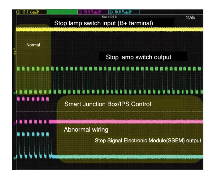
Analyze diagnostic tool data and confirm if there is anything wrong
with the stop lamp switch.
|


| Removal |
| 1. |
Turn ignition switch OFF and disconnect the negative (-) battery cable.
|
| 2. |
Remove the lower crash pad.
(Refer to Body - "Crash Pad")
|
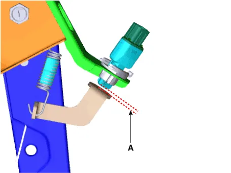
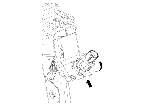
| 3. |
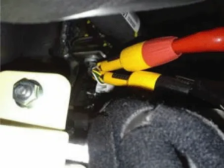
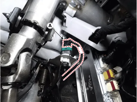
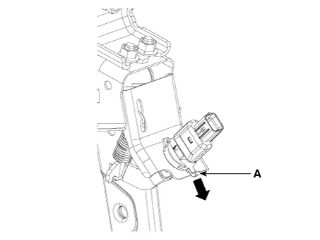
Disconnect the stop lamp switch connector (A).
|
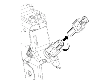
| 4. |
Pull the locking plate (A) as indicated by the arrow.
|
| 5. |
Turn stop lamp switch (A) 45° counterclockwise and remove it.
|
| 6. |
Inspect a removed stop lamp switch along the below procedures.
|
| Installation |
| 1. |
Fix the brake pedal arm and insert fully the stop lamp switch as hiding
contact part.
|
| 2. |
After inserting, turn the stop switch (A) 45° clockwise, and then assemble
locking plate by pushing.
|
| 3. |
Confirm the gap between stop lamp switch and bracket.
|

| 4. |
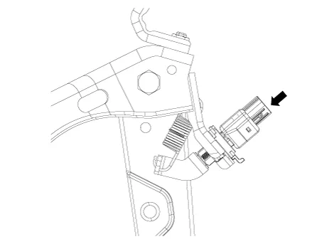
Connect the stop lamp switch connector (A).
|
| 5. |
Install the lower crash pad.
(Refer to Body - "Crash Pad")
|
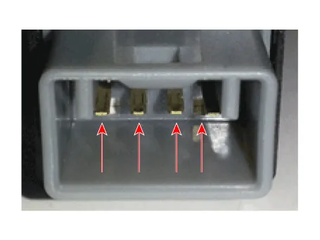
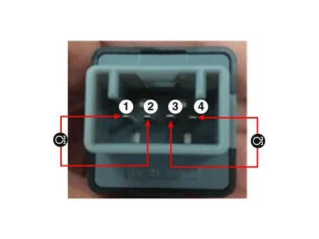
Schematic Diagram System circuit diagram Terminal Function Teminal Description 1 IGN1 2 Engine Control Module (ECM) 3 - 4 B+ 5 Stop Lamp 6 Gruound
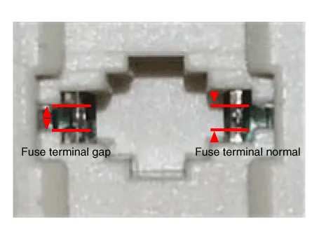
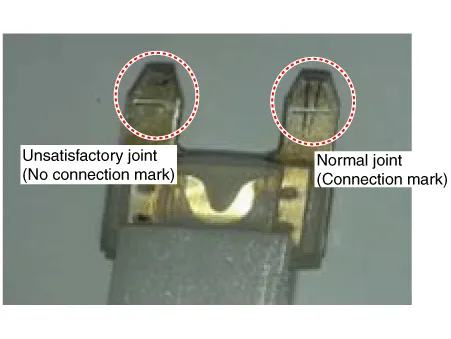
Troubleshooting 1. Part diagnosis Items Cause Symptom Switch fuse Faulty fuse connection, Damaged fuse – DTC Code : P0504 – Symptom : Shifting gear trouble, Starting failure, Cruise control function cancelation trouble, EPB function cancelation trouble, Stop lamp lighting trouble, ESP OFF light illuminated.
Other information:
Hyundai Santa Fe (TM) 2019-2023 Service and Repair Manual: Smart Key. Repair procedures
Smart Key Smart Key Code Saving 1. Connect the DLC cable of diagnostic tool to the data link connector (16 pins) in driver side crash pad lower panel, turn the power on diagnostic tool. 2.
Hyundai Santa Fe (TM) 2019-2023 Service and Repair Manual: In-car Sensor. Description and operation
Description The In-car air temperature sensor is built in the heater & A/C control unit. The sensor consists of a thermistor that measures the inside temperature. The signal decided by the resistance value that changes in accordance with perceived inside temperature, is delivered to heater control unit, and according t
Categories
- Manuals Home
- Hyundai Santa Fe Owners Manual
- Hyundai Santa Fe Service Manual
- Rear Disc Brake. Repair procedures
- Battery. Specifications
- Engine Mechanical System
- New on site
- Most important about car
