Hyundai Santa Fe (TM): Smart Key System / Smart Key Diagnostic. Repair procedures
Hyundai Santa Fe (TM) 2019-2023 Service and Repair Manual / Body Electrical System / Smart Key System / Smart Key Diagnostic. Repair procedures
| Inspection |
Self Diagnosis With Scan Tool
It will be able to diagnose defects of SMART KEY system with diagnostic tool
quickly. diagnostic tool can operates actuator forcefully, input/output value
monitoring and self diagnosis.
The following three features will be major problem in SMART KEY system.
| 1. |
Problem in SMART KEY unit input.
|
| 2. |
Problem in SMART KEY unit.
|
| 3. |
Problem in SMART KEY unit output.
|
So the following three diagnosis operates will be the major problem solution
process.
| 4. |
SMART KEY unit Input problem : switch diagnosis
|
| 5. |
SMART KEY unit problem : communication diagnosis
|
| 6. |
SMART KEY unit Output problem : antenna and switch output diagnosis
|
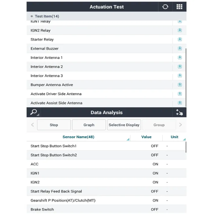
Switch Diagnosis
| 1. |
In the body electrical system, failure can be quickly diagnosed by using
the vehicle diagnostic system (diagnostic tool).
The diagnostic system(diagnostic tool) provides the following information.
|
| 2. |
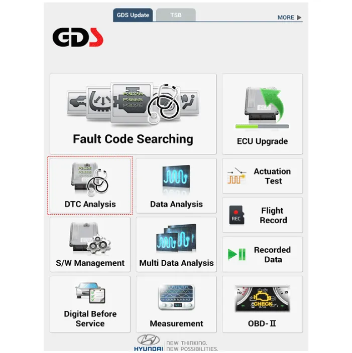
If diagnose the vehicle by diagnostic tool, select "DTC Analysis" and
"Vehicle".
|
| 3. |
If check current status, select the "Data Analysis" and "Car model".
|

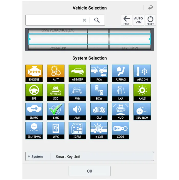
| 4. |
Select the SMK' to be checked in order to check the vehicle with the
tester.
|
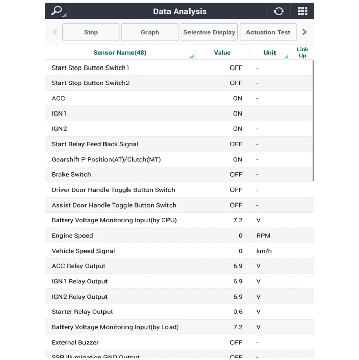
| 5. |
You can see the situation of each switch on scanner after connecting
the "current data" process.
|
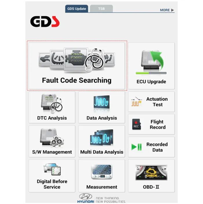
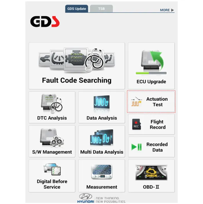
Fault Code Searching
| 1. |
Fault code searching that the each linked components operates normal.
|
| 2. |
Connect the cable of diagnostic tool to the data link connector in driver
side crash pad lower panel.
|
| 3. |
Select the 'Fault Code Searching' and 'Car model'.
|
Antenna Actuation Diagnosis
| 1. |
Connect the cable of diagnostic tool to the data link connector in driver
side crash pad lower panel.
|
| 2. |
Select the 'Actuation Test' and 'Car model'.
|
| 3. |
Set the smart key near the related antenna and operate it with a diagnostic
tool.
|
| 4. |
Set the smart key near the related antenna and operate it with a diagnostic
tool.
|
| 5. |
If the LED of smart key is blinking, the smart key is normal.
|
| 6. |
If the LED of smart key is not blinking, check the voltage of smart
key battery.
|
| 7. |
Antenna actuation
|
Antenna Status Check
| 1. |
Connect the cable of diagnostic tool to the data link connector in driver
side crash pad lower panel.
|
| 2. |
Select the 'S/W Management' and 'Car model'.
|

| 3. |
Select the 'Smart Key Unit' and 'Antenna Status Check'.
|

| 4. |
Set the smart key near the related antenna and operate it with a diagnostic
tool.
|
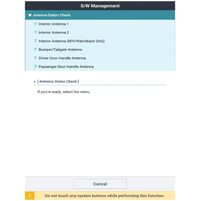
| 5. |
If the smart key runs normal , the related antenna, smart key(transmission,
reception) and exterior receiver are normal.
|
| 6. |
Antenna status
|
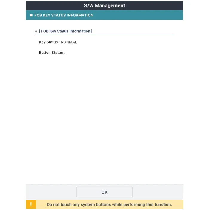
FOB Status Check
| 1. |
Connect the cable of diagnostic tool to the data link connector in driver
side crash pad lower panel.
|
| 2. |
Select the 'S/W Management' and 'Car model'.
|
| 3. |
Select the 'Smart Key Unit' and 'FOB KEY STATUS IMFORMATION'.
|

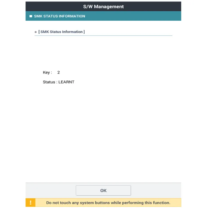
Smart Key Status Check
| 1. |
Connect the cable of diagnostic tool to the data link connector in driver
side crash pad lower panel.
|
| 2. |
Select the 'S/W Management' and 'Car model'.
|
| 3. |
Select the 'Smart Key Unit' and 'SMK STATUS INFORMATION'.
|

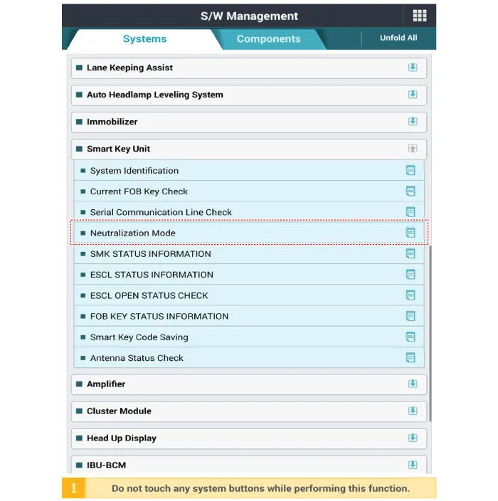
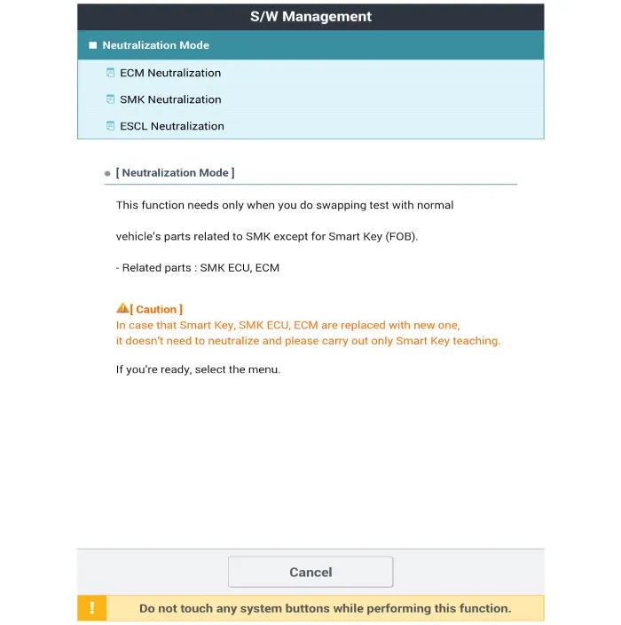
Neutralization Status Check
| 1. |
Connect the cable of diagnostic tool to the data link connector in driver
side crash pad lower panel.
|
| 2. |
Select the 'S/W Management' and 'Car model'.
|
| 3. |
Select the 'Smart Key Unit' and 'Neutralization Mode'.
|
Removal Integrated Body Control Unit (IBU) 1. Disconnect the negative (-) battery terminal. 2.
Removal Interior 1 Antenna Take care not to scratch the crash pad and related parts.
Other information:
Hyundai Santa Fe (TM) 2019-2023 Service and Repair Manual: Smart Key Unit. Components and components location
Hyundai Santa Fe (TM) 2019-2023 Service and Repair Manual: Surround View Monitor (SVM)
Description and operation Description Surround View Monitor (SVM) is the system that allows video monitoring of 360 degrees around the vehicle. The system includes 4 ultra optical camera mounted around the vehicle (front, both sides, rear).
Categories
- Manuals Home
- Hyundai Santa Fe Owners Manual
- Hyundai Santa Fe Service Manual
- Restraint
- Blower
- Auto Hold. Warning messages
- New on site
- Most important about car

Copyright © 2026 www.hsafe4.com - 0.0308