Hyundai Santa Fe (TM): Brake System / Stop Lamp Switch. Components and components location
| Components |
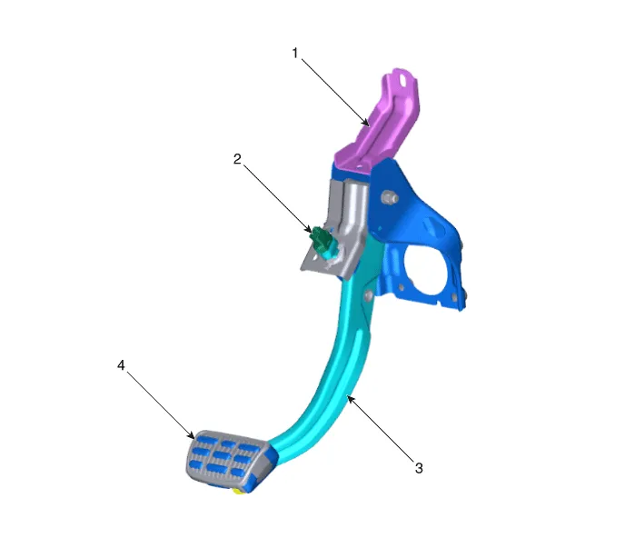
| 1. Brake member
assembly 2. Stop lamp switch |
3. Brake pedal
arm assembly 4. Brake pedal pad |
Replacement • Be careful not to damage the parts located under the vehicle (floor under cover, fuel filter, fuel tank and canister) when raising the vehicle using the lift.
Schematic Diagram System circuit diagram Terminal Function Teminal Description 1 IGN1 2 Engine Control Module (ECM) 3 - 4 B+ 5 Stop Lamp 6 Gruound
Other information:
Hyundai Santa Fe (TM) 2019-2023 Service and Repair Manual: Integrated Body Control Unit (IBU)
Description and operation Description Body Control Module Controls The Followings – Wiper & Washer Control – Defroster Control – Driving Control – Tailgate Control – Window Contr
Hyundai Santa Fe (TM) 2019-2023 Service and Repair Manual: Cruise Control System (CC)
Description and operation Description The cruise control system is engaged by the cruise "ON/OFF" main switch located on right of steering wheel column. The system has the capability to cruise, coast, accelerate and resume speed.
Categories
- Manuals Home
- Hyundai Santa Fe Owners Manual
- Hyundai Santa Fe Service Manual
- Front Radar Unit. Repair procedures
- Auto Hold. Warning messages
- Electronic Parking Brake (EPB)
- New on site
- Most important about car
