Hyundai Santa Fe (TM): Brake System / Stop Lamp Switch. Components and components location
| Components |
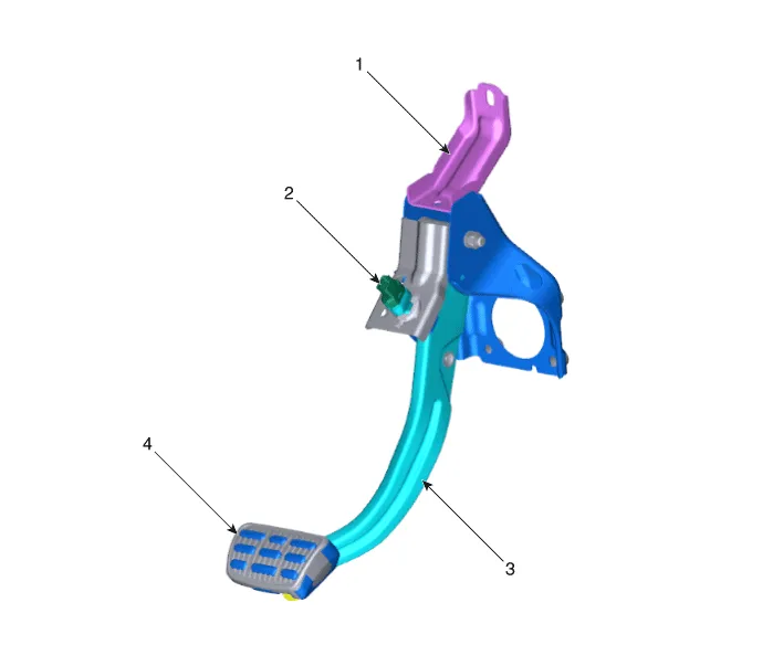
| 1. Brake member
assembly 2. Stop lamp switch |
3. Brake pedal
arm assembly 4. Brake pedal pad |
Replacement • Be careful not to damage the parts located under the vehicle (floor under cover, fuel filter, fuel tank and canister) when raising the vehicle using the lift.
Schematic Diagram System circuit diagram Terminal Function Teminal Description 1 IGN1 2 Engine Control Module (ECM) 3 - 4 B+ 5 Stop Lamp 6 Gruound
Other information:
Hyundai Santa Fe (TM) 2019-2023 Service and Repair Manual: Rear Occupant Alert
Description and operation Description The system detects the passenger in the vehicle and prevents the driver from getting off the vehicle with the passenger in the back. - 1st warning: If you open the driver's door after you open and then close the rear passenger and turn the engine off, the system provides warn
Hyundai Santa Fe (TM) 2019-2023 Service and Repair Manual: Front Radar Unit. Repair procedures
Inspection Inspection procedure for vehicle with Forward Collision-Avoidance Assist and Smart Cruise Control system failure 1. Check the bumper appearance for accident (check the vehicle appearance visually and see bumper replacement history).
Categories
- Manuals Home
- Hyundai Santa Fe Owners Manual
- Hyundai Santa Fe Service Manual
- Instrument cluster
- Lane Following Assist (LFA)
- Gauges and meters
- New on site
- Most important about car
