Hyundai Santa Fe: Starting System / Starter. Repair procedures
Hyundai Santa Fe (TM) 2019-2025 Service Manual / Engine Electrical System / Starting System / Starter. Repair procedures
| Removal |
|

| 1. |
Turn the ignition switch OFF and disconnect the battery (-) terminal.
|
| 2. |
Remove the engine room under cover.
(Refer to Engine Mechanical System - "Engine Room Under Cover")
|
| 3. |
Disconnect the starter ST connector (A).
|
| 4. |
Remove the stater "B" terminal cable mounting nut (B).
|
| 5. |
Remove the starter mounting bolt (A).
|
| 6. |
Remove the starter.
|
| Installation |
| 1. |
Install in the reverse order of removal.
|
| Disassembly |
| 1. |
Disconnect the M-terminal (A) on the magnetic switch assembly.
|
| 2. |
After loosening the screws (A), remove the magnetic switch assembly
(B).
|

| 3. |
Loosen the through bolts (A) and then separate the brush holder assembly
& rear bracket assembly from the front bracket assembly.
|
| 4. |
Remove the lever lest (A).
|
| 5. |
Remove the lever (A).
|
| 6. |
Detach the planet gear shaft assembly (A), brush holder assembly (B),
armature assembly (C) and yoke assembly (D).
|
| 7. |
Remove the shield (A).
|
| 8. |
Remove the planet gears (A).
|
| 9. |
Press the stopper (A) using a socket (B).
|
| 10. |
Remove the stop ring (A) using the stop ring pliers (B).
|

| 11. |
Remove the stopper (A), overrunning clutch (B), internal gear (C) and
planet shaft (D).
|

| Reassembly |
| 1. |
Reassemble in the reverse order of disassembly.
|
| Inspection |
Starter Solenoid Inspection
| 1. |
Disconnect the lead wire from the M-terminal of solenoid switch.
|
| 2. |
Connect the battery as shown. If the starter pinion pops out, it is
working properly.
|
| 3. |
Disconnect the battery from the M terminal.
If the pinion does not retract, the hold-in coil is working properly.
|
| 4. |
Disconnect the battery also from the body. If the pinion retracts immediately,
it is working properly.
|
Free Running Inspection
| 1. |
Place the starter motor in a vise equipped with soft jaws and connect
a fully-charged 12-volt battery to starter motor as follows.
|
| 2. |
Connect a test ammeter (150-ampere scale) and carbon pile rheostats
shown is the illustration.
|
| 3. |
Connect a voltmeter (15-volt scale) across starter motor.
|
| 4. |
Rotate carbon pile to the off position.
|
| 5. |
Connect the battery cable from battery's negative post to the starter
motor body.
|
| 6. |
Adjust until battery voltage shown on the voltmeter reads 11.5 and 11
volts.
|
| 7. |
Confirm that the maximum amperage is within the specifications and that
the starter motor turns smoothly and freely.
|
Armature Inspection and Test
| 1. |
Remove the starter.
|
| 2. |
Disassemble the starter as shown at the beginning of this procedure.
|
| 3. |
Inspect the armature for wear or damage from contact with the permanent
magnet. If there is wear or damage, replace the armature.
|
| 4. |
Check the commutator (A) surface. If the surface is dirty or burnt,
resurface with emery cloth or a lathe within the following specifications,
or recondition with #500 or #600 sandpaper (B).
|
| 5. |
Measure the commutator (A) runout.
|
| 6. |
Check the mica depth (A). If the mica is too high (B), undercut the
mica with a hacksaw blade to the proper depth. Cut away all the mica
(C) between the commutator segments. The undercut should not be too
shallow, too narrow, or v-shaped (D).
|
| 7. |
Check for continuity between the segments of the commutator. If an open
circuit exists between any segments, replace the armature.
|
| 8. |
Check with an ohmmeter that no continuity exists between the commutator
(A) and armature coil core (B), and between the commutator and armature
shaft (C). If continuity exists, replace the armature.
|
Inspect Starter Brush
Any worn out or oil-soaked brushes should be replaced.
Starter Brush Holder Test
| 1. |
Check that there is no continuity between the (+) brush holder (A) and
(-) plate (B). If there is continuity, replace the brush holder assembly.
|
Inspect Overrunning Clutch
| 1. |
Slide the overrunning clutch along the shaft.
Replace if it does not slide smoothly.
|
| 2. |
Rotate the overrunning clutch both ways.
Does it lock in one direction and rotate smoothly in reverse? If it
does not lock in either direction or locks in both directions, replace
it.
|
| 3. |
If the starter drive gear is worn or damaged, replace the overrunning
clutch assembly. (The gear is not available separately.)
Check the condition of the flywheel or torque converter ring gear if
the starter drive gear teeth are damaged.
|
| Cleaning |
| 1. |
Do not immerse parts in cleaning solvent.
Immersing the yoke assembly and/or armature will damage the insulation
wipe these parts with a cloth only.
|
| 2. |
Do not immerse the drive unit in cleaning solvent.
The overrun clutch is pre-lubricated at the factory and solvent will
wash lubrication from the clutch.
|
| 3. |
The drive unit may be cleaned with a brush moistened with cleaning solvent
and wiped dry with a cloth.
|

 Starter Relay. Repair procedures
Inspection
1.
Turn ignition switch OFF and disconnect the battery negative (-) terminal.
2.
Remove the fuse box cover...
Other information:
Hyundai Santa Fe (TM) 2019-2025 Service Manual: Rear Door Outside Handle. Components and components location
..
Hyundai Santa Fe (TM) 2019-2025 Service Manual: Trailing Arm. Repair procedures
Removal 1. Loosen the wheel nuts slightly. Raise the vehicle, and make sure it is securely supported. 2. Remove the rear wheel and tire (A) from rear hub. Tightening torque : 107...
Categories
- Manuals Home
- 4th Generation Santa Fe Owners Manual
- 4th Generation Santa Fe Service Manual
- Body (Interior and Exterior)
- Gauges and meters
- Smart liftgate
- New on site
- Most important about car
Vehicle Identification Number (VIN). Vehicle certification label. Tire specification and pressure label
Vehicle Identification Number (VIN)
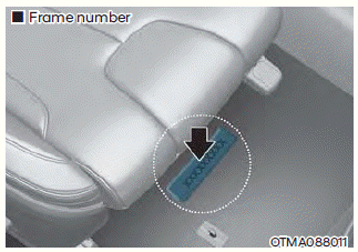
The vehicle identification number (VIN) is the number used in registering your vehicle and in all legal matters pertaining to its ownership, etc.
The number is punched on the floor under the passenger seat. To check the number, open the cover.

Copyright © 2025 www.hsafe4.com