Hyundai Santa Fe (TM): Rear Driveshaft Assembly / Repair procedures
Hyundai Santa Fe (TM) 2019-2023 Service and Repair Manual / Driveshaft and axle / Rear Driveshaft Assembly / Repair procedures
| Removal |
|

| 1. |
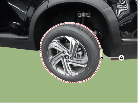
Loosen the wheel nuts slightly.
Raise the vehicle, and make sure it is securely supported.
|
| 2. |
Remove the rear wheel and tire (A) from rear hub.
|

| 3. |
Remove the rear brake caliper.
(Refer to Brake System - "Rear Disc Brake")
|
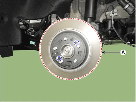
| 4. |
Loosen the screw and then removing the rear brake disc (A).
|
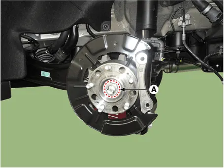
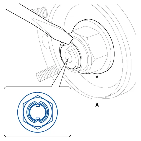
| 5. |
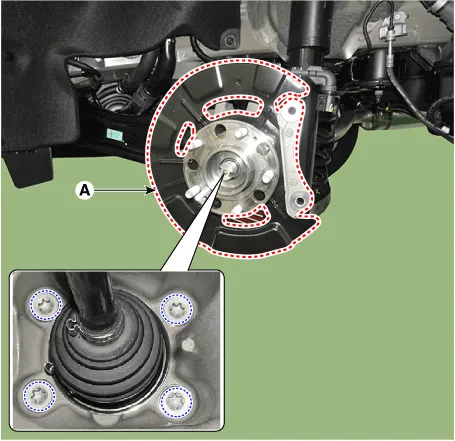
Loosen the driveshaft caulking nut (A) from the rear hub.
|
| 6. |
Remove the rear hub assembly and dust cover (A) after loosening the
mounting bolts.
|
| 7. |
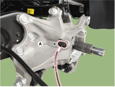
Remove the rear wheel speed sensor (A) after loosening the mounting
bolt.
|
| 8. |
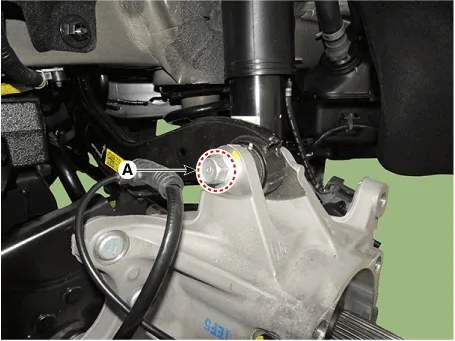
Remove the rear upper arm from the rear carrier after loosening the
bolt and nut (A).
|
| 9. |
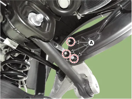
Remove the trailing arm from the rear carrier after loosening the mounting
nuts (A).
|
| 10. |
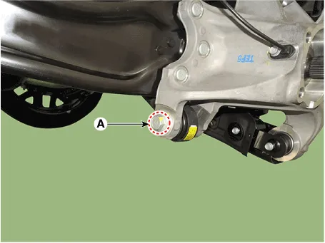
Remove the rear assist arm from the rear carrier after loosening the
bolt and nut (A).
|
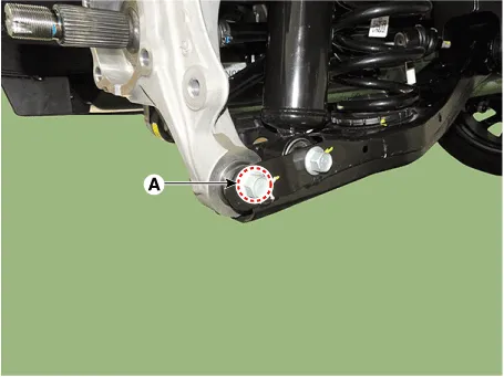
| 11. |
Remove the rear lower arm from the rear carrier after loosening the
bolt and nut (A).
|
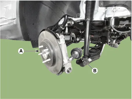
| 12. |
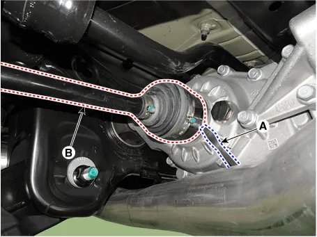
Remove the rear drive shaft (B) from the rear axle assembly (A).
|
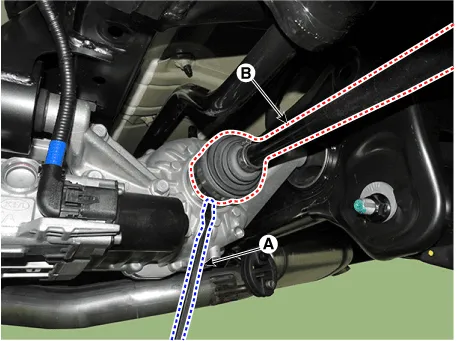
| 13. |
Remove the rear drive shaft (B) from the differential by using the pry
bar (A).
[LH]
[RH]
|
| Inspection |
| 1. |
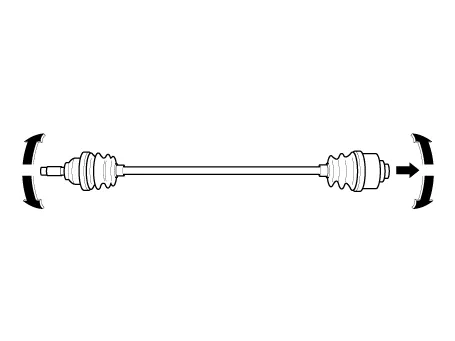
Check the driveshaft boots for damage and deterioration.
|
| 2. |
Check the ball joint for wear and damage.
|
| 3. |
Check the splines for wear and damage.
|
| 4. |
Check the driveshaft for cracks and wears.
|
| 5. |
Check the TJ outer race, inner race, cage and balls for rust or damage.
|
| 6. |
Check for water, foreign matter, or rust in the BJ boot.
|
| Disassembly |
|
| 1. |
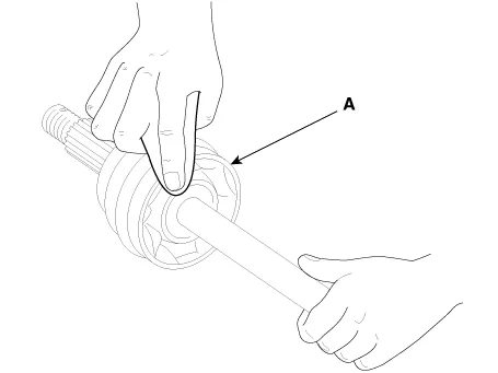
Remove the TJ boot bands and pull the TJ boot from the TJ outer race.
|
| 2. |
Pull out the driveshaft from the TJ outer race.
|
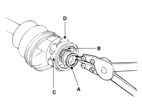
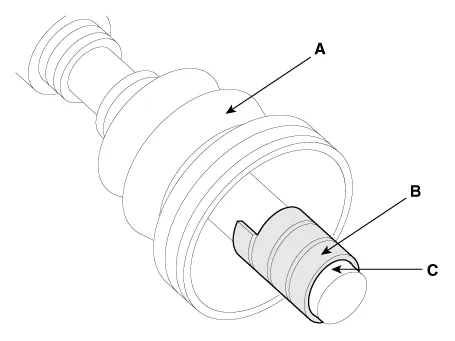
| 3. |
Remove the snap ring (A) and take out the inner race(B), cage(C) and
balls(D) as an assembly.
|
| 4. |
Clean the inner race, cage and balls without disassembling.
|
| 5. |
Remove the BJ boot bands and pull out the TJ boot and BJ boot.
|
| Reassembly |
| 1. |
Wrap tape around the driveshaft splines (TJ side ) to prevent damage
to the boots.
|
| 2. |
Apply grease to the driveshaft and install the boots.
|
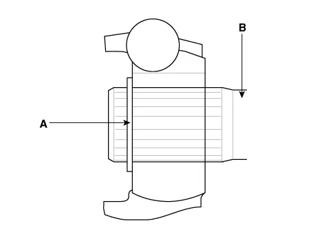
| 3. |
Apply the specified grease to the inner race (A) and cage (B). Install
the cage (B) so that it is offset on the race as shown.
|
| 4. |
Apply the specified grease to the cage and fit the balls into the cage.
|
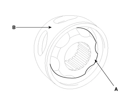
| 5. |
Position the chamfered side (A) as shown in the illustration. Install
the inner race on the driveshaft(B), and then the snap ring.
|
| 6. |
Apply the specified grease to the outer race and install the BJ outer
race onto the driveshaft.
|
| 7. |
Apply the specified grease into the TJ boot and install the boot with
a clip.
|
| 8. |
Tighten the TJ boot bands.
|
| 9. |
Add the specified grease to the BJ as much as wiped away at inspection.
|
| 10. |
Install the boots.
|
| 11. |
Tighten the BJ boot bands.
|
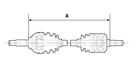
| 12. |
To control the air in the TJ boot, keep the specified distance between
the boot bands when they are tightened.
|
| Installation |
| 1. |
To install, reverse the removal procedures.
|
| 2. |
Check the alignment.
(Refer to Suspension System - "Alingment")
|
Components 1. Rear drive shaft (left) 2. Rear drive shaft (right)
Other information:
Hyundai Santa Fe (TM) 2019-2023 Service and Repair Manual: Intake Actuator. Repair procedures
Inspection 1. Turn the ignition switch OFF. 2. Disconnect the intake actuator connector. 3. Verify that the intake actuator operates to the fresh air position when connecting 12V to terminal 3 and grounding terminal 7.
Hyundai Santa Fe (TM) 2019-2023 Service and Repair Manual: Front View Camera Unit. Repair procedures
Removal 1. Disconnect the negative (-) battery terminal. 2. Remove the inside rear view mirror cover (A) and front view camera cover (B). 3.
Categories
- Manuals Home
- Hyundai Santa Fe Owners Manual
- Hyundai Santa Fe Service Manual
- Front Radar Unit. Repair procedures
- Forward Collision-Avoidance Assist Settings
- Driver assistance system
- New on site
- Most important about car

Copyright © 2025 www.hsafe4.com - 0.0148