|
If the plasticgauge shows that the clearance is still incorrect,
try the next larger or smaller bearing (the color listed above
or below that one), and check clearance again.
|
• |
If the proper clearance cannot be obtained by
using the appropriate larger or smaller bearings,
replace the crankshaft and start over.
|
|
• |
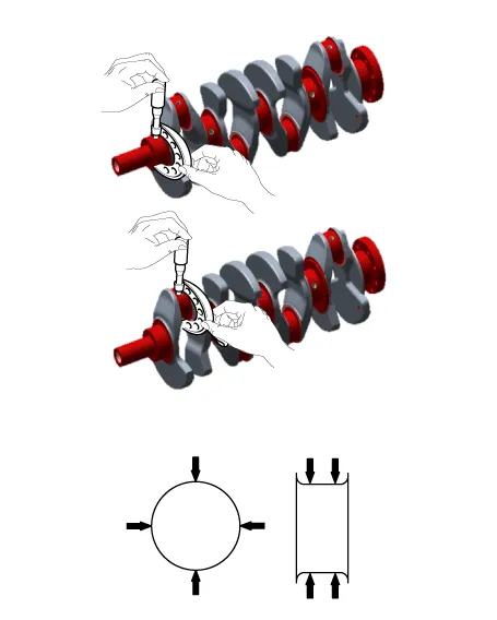
If the marks are indecipherable because of an
accumulation of dirt and dust, do not scrub
them with a wire brush or scraper. Clean them
only with solvent or detergent.
|
|
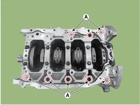
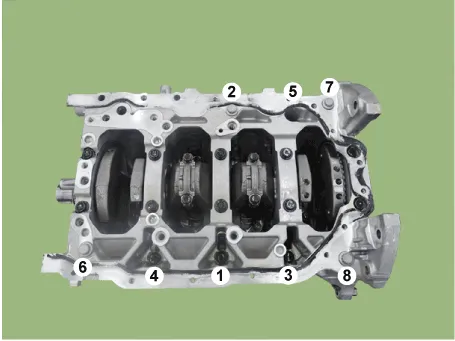
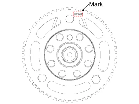
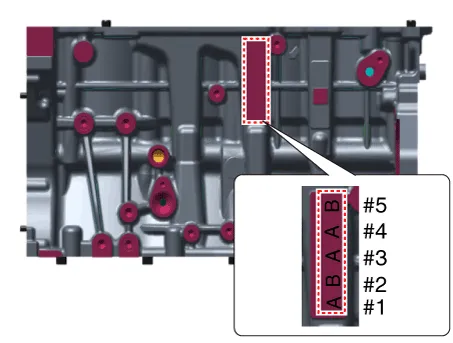
Cylinder Block Crankshaft Journal Bore Mark Location
Letters have been stamped on the side surface of the block as
a mark for the size of each of the 5 main journal bores.
Use them, and the numbers or letters stamped on the crank (marks
for main journal size), to choose the correct bearings.
Class
|
Mark
|
Cylinder block crankshaft journal bore inner diameter
|
a
|
A
|
57.000 - 57.006 mm
(2.2441 - 2.2443 in.)
|
b
|
B
|
57.006 - 57.012 mm
(2.2443 - 2.2446 in.)
|
c
|
C
|
57.012 - 57.018 mm
(2.2446 - 2.2448 in.)
|
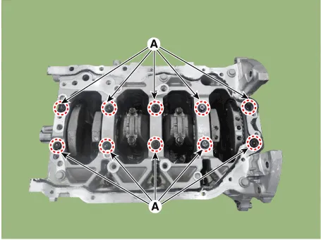
Crankshaft Main Journal Mark Location
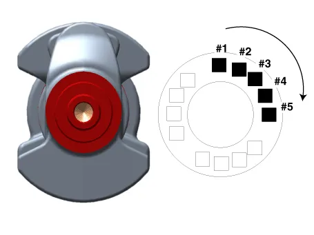
Discrimination Of Crankshaft Main Journal
Class
|
Mark
|
Crankshaft main journal outer diameter
|
A
|
1
|
51.954 - 51.960 mm
(2.0454 - 2.0457 in.)
|
B
|
2
|
51.948 - 51.954 mm
(2.0452 - 2.0454 in.)
|
C
|
3
|
51.942 - 51.948 mm
(2.0450 - 2.0452 in.)
|
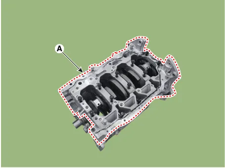
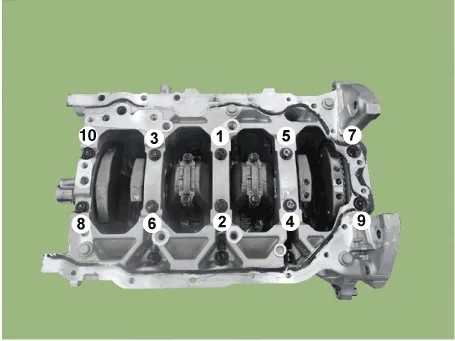
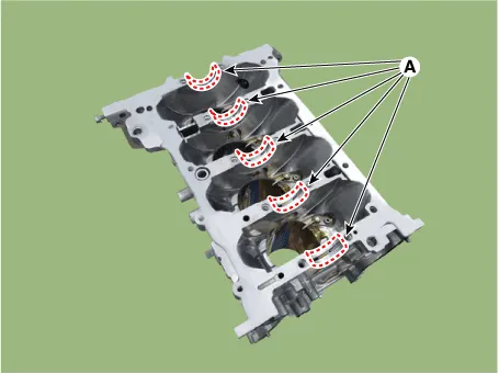
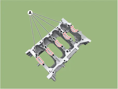
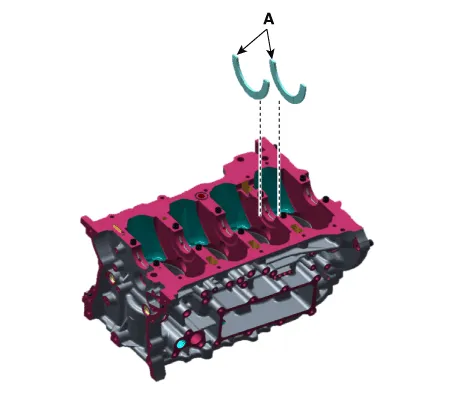
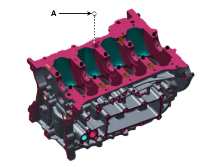
Crankshaft Bearing Identification Mark Location
[No. 2, No 3, No. 4 Journal Upper Bearing]
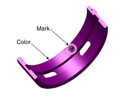
[No. 1, No 5 Journal Upper Bearing]
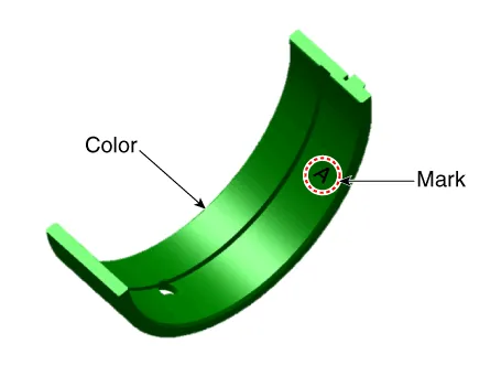
[Lower Bearing]
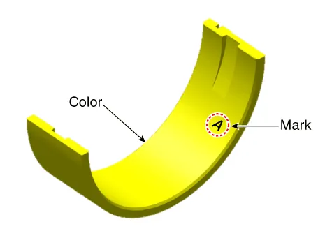
Discrimination Of Crankshaft Bearing
Class
|
Color
|
Bearing thickness
|
A
|
LIGHT Blue
|
2.518 - 2.521mm
(0.0991 - 0.0993in.)
|
B
|
Black
|
2.515 - 2.518mm
(0.0990 - 0.0991in.)
|
C
|
WHITE
|
2.512 - 2.515mm
(0.0989 - 0.0990in.)
|
D
|
LIGT GREEN
|
2.509 - 2.512mm
(0.0988 - 0.0989in.)
|
E
|
PINK
|
2.506 - 2.509 mm
(0.0987 - 0.0988 in.)
|
F
|
YELLOW
|
2.503 - 2.506 mm
(0.0985 - 0.0987 in.)
|
|