Hyundai Santa Fe (TM): Engine Control System / Variable Force Solenoid (VFS). Repair procedures
Hyundai Santa Fe (TM) 2019-2023 Service and Repair Manual / Engine Control/Fuel System / Engine Control System / Variable Force Solenoid (VFS). Repair procedures
| Inspection |
| 1. |
Turn the ignition switch OFF.
|
| 2. |
Disconnect the OCV connector.
|
| 3. |
Measure resistance between the OCV terminals 1 and 2.
|
| 4. |
Check that the resistance is within the specification.
|
| Removal |
| 1. |
Turn the ignition switch OFF and disconnect the battery negative (-)
cable.
|
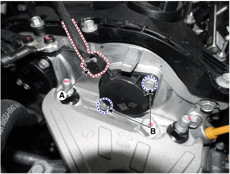
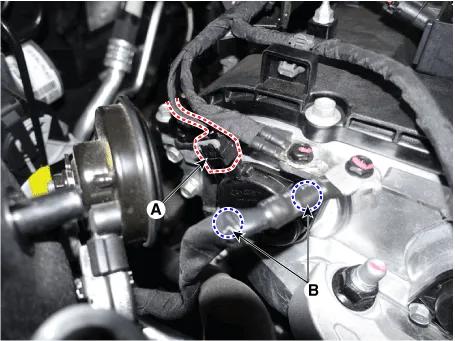
| 2. |
Disconnect the CVVT oil control valve connector (A).
|
| 3. |
Remove the installation bolt (B), and then remove the valve from the
engine.
[Bank 1 / Intake]
[Bank 1 / Exhaust]
|
| Installation |
|

|
| 1. |
Installation is reverse of removal.
|
Circuit Diagram Harness Connector
Description Variable Intake manifold Solenoid (VIS) valve is installed on the intake manifold. The VIS valve controls the vacuum modulator which activates a valve in the intake manifold.
Other information:
Hyundai Santa Fe (TM) 2019-2023 Service and Repair Manual: Heater
Heater Unit. Components and components location Component Location 1. Heater Unit Assembly Components 1. Heater unit assembly 2. Heater NVH pad 3. Heater seal duct 4.
Hyundai Santa Fe (TM) 2019-2023 Service and Repair Manual: Smart Cruise Control (SCC) Switch. Components and components location
Categories
- Manuals Home
- Hyundai Santa Fe Owners Manual
- Hyundai Santa Fe Service Manual
- Auto Hold. Warning messages
- 4 Wheel Drive (4WD) System
- Hydraulic System
- New on site
- Most important about car

Copyright © 2026 www.hsafe4.com - 0.0228