Hyundai Santa Fe (TM): Automatic Transaxle Control System / Input Speed Sensor. Repair procedures
| Inspection |
|

| Removal |
|

| 1. |
Turn ignition switch OFF and disconnect the negative (-) battery cable.
|
| 2. |
Remove the air duct and the air cleaner assembly.
(Refer to Engine Mechanical System - "Air Cleaner")
|
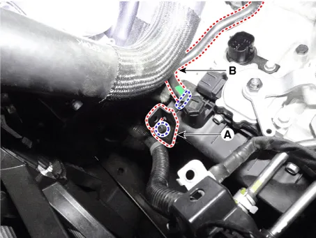
| 3. |
Separate the air bleed hose (B) and then wiring bracket (A).
|
| 4. |
Remove the under cover.
(Refer to Engine Mechanical System - "Engine Room Under Cover")
|
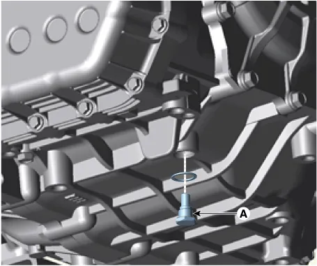
| 5. |
Remove the drain plug (A) and reinstall the drain plug after draining
ATF totally.
|
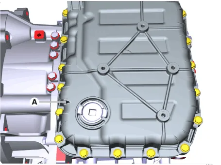
| 6. |
Loosen the mounting bolts (A) of the valve body cover.
|
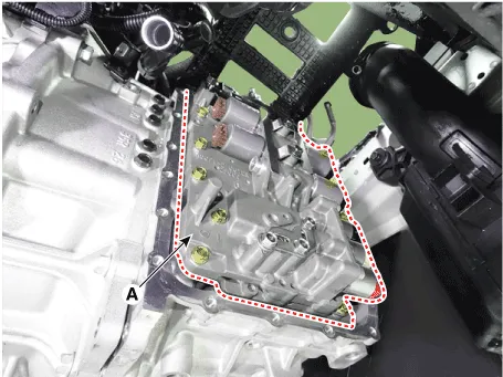
| 7. |
Loosen the bolts and then removing the main harness (A).
|
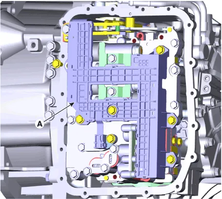
| 8. |
Loosen the mounting bolts and then removing the valve body assembly
(A).
|
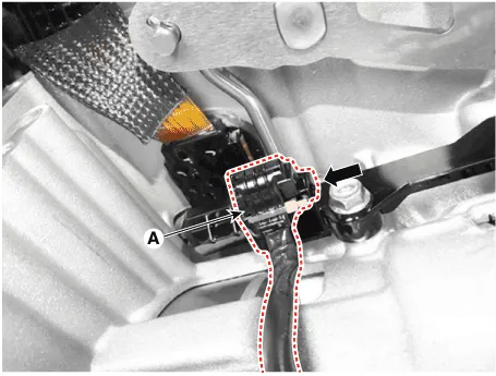
| 9. |
Disconnect the input & output speed sensor connector (A).
|
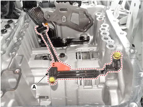
| 10. |
Loosen the bolts and then removing the input / output speed sensor (A).
|
| Installation |
| 1. |
To install, reverse the removal procedure.
|
| 2. |
Check fluid level after filling the automatic transaxle with fluid.
(Refer to Automatic Transaxle Syatem-"Automatic Transaxle Fluid(ATF)")
|
Specifications ▷ Type : Hall effect sensor ▷ Specifications Items Specifications Operation condition [°C(°F)] (-40 to 150) -40 to 302 Sensor length (mm) 35.
Description The output speed sensor is a vital unit that measures the rate of rotation of the transaxle's turbine shaft and output shaft, and delivers the readings to the TCM.
Other information:
Hyundai Santa Fe (TM) 2019-2023 Service and Repair Manual: Specifications
Specifications Smart Key Unit Items Specification Rated voltage DC 12V Operating voltage DC 9 - 16V Operating temperature -22°F to 167°F (-30°C to- 75°C) Load Max.
Hyundai Santa Fe (TM) 2019-2023 Service and Repair Manual: Rear Occupant Alert
Description and operation Description The system detects the passenger in the vehicle and prevents the driver from getting off the vehicle with the passenger in the back. - 1st warning: If you open the driver's door after you open and then close the rear passenger and turn the engine off, the system provides warn
Categories
- Manuals Home
- Hyundai Santa Fe Owners Manual
- Hyundai Santa Fe Service Manual
- Emission Control System
- Rear Disc Brake. Repair procedures
- 4 Wheel Drive (4WD) System
- New on site
- Most important about car
