Hyundai Santa Fe (TM): Engine Control System / Variable Intake Solenoid (VIS) Valve. Repair procedures
Hyundai Santa Fe (TM) 2019-2023 Service and Repair Manual / Engine Control/Fuel System / Engine Control System / Variable Intake Solenoid (VIS) Valve. Repair procedures
| Inspection |
| 1. |
Turn the ignition switch OFF.
|
| 2. |
Disconnect the VIS valve connector.
|
| 3. |
Measure resistance between VIS valve terminals 1 and 2.
|
| Removal |
| 1. |
Turn the ignition switch OFF and disconnect the battery negative (-)
cable.
|
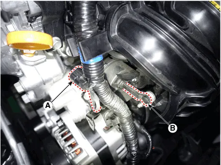
| 2. |
Disconnect the variable intake solenoid valve connector (A).
|
| 3. |
Disconnect the vacuum link (B) from the valve.
|
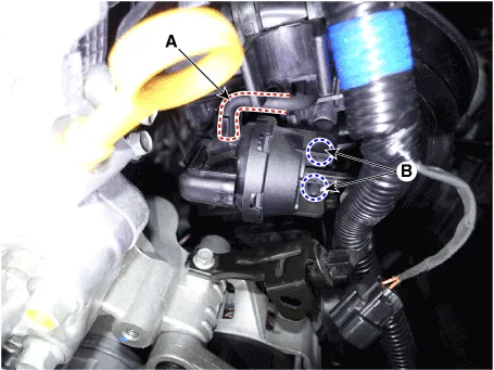
| 4. |
Disconnect the vacuum hoses (A) from the valve.
|
| 5. |
Remove the installation bolt (B), and then remove the valve from the
surge tank.
|
| Installation |
|

|
| 1. |
Installation is reverse of removal.
|
Circuit Diagram Harness Connector
Components and components location Components Location 1. Fuel tank 2. Fuel pump 3. Fuel filter 4. Fuel pump motor 5.
Other information:
Hyundai Santa Fe (TM) 2019-2023 Service and Repair Manual: Special service tools
Hyundai Santa Fe (TM) 2019-2023 Service and Repair Manual: Ambient Temperature Sensor. Repair procedures
Inspection 1. Check the resistance of the ambient temperature sensor between terminals 1 and 2 whether it changes by changing the ambient temperature. 1. Ambient Sensor (+) 2.
Categories
- Manuals Home
- Hyundai Santa Fe Owners Manual
- Hyundai Santa Fe Service Manual
- Tire Pressure Monitoring System (TPMS)
- Power Tailgate Module
- Gauges and meters
- New on site
- Most important about car

Copyright © 2026 www.hsafe4.com - 0.018