Hyundai Santa Fe (TM): Hydraulic System / Valve Body. Repair procedures
| Removal |
|

| 1. |
Turn ignition switch OFF and disconnect the negative (-) battery cable.
|
| 2. |
Remove the air duct and the air cleaner assembly.
(Refer to Engine Mechanical System - "Air Cleaner")
|
| 3. |
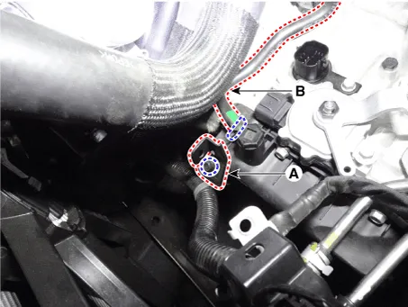
Separate the air bleed hose (B) and then wiring bracket (A).
|
| 4. |
Remove the under cover.
(Refer to Engine Mechanical System - "Engine Room Under Cover")
|
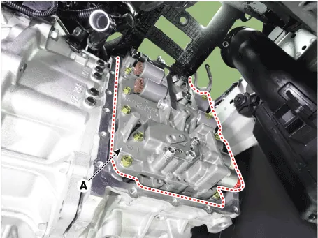
| 5. |
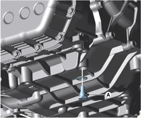
Remove the drain plug (A) and reinstall the drain plug after draining
ATF totally.
|
| 6. |
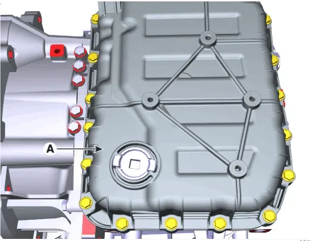
Loosen the mounting bolts (A) of the valve body cover.
|
| 7. |
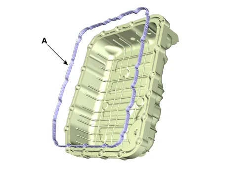
Loosen the bolts and then removing the main harness (A).
|
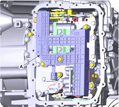
| 8. |
Loosen the mounting bolts and then removing the valve body assembly
(A).
|
| Installation |
| 1. |
To install, reverse the removal procedure.
|
| 2. |
Check the ATF level after refilling the automatic transaxle with fluid.
(Refer to Automatic Transaxle System - "Automatic Transaxle Fluid (ATF)"
)
|
| 3. |
Clear the diagnostic trouble codes (DTC) using the diagnostic tool.
(Refer to Automatic Transaxle System - "Automatic Transaxle System"
)
|
| 4. |
Reset the automatic transaxle adaptive values using the diagnostic tool.
|

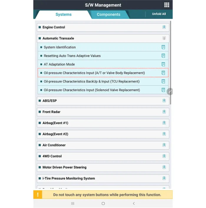
| 5. |
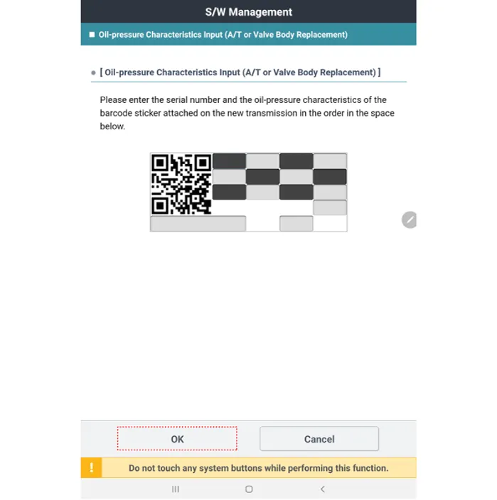
Perform the oil pressure characteristics input (A/T or valve body replacement)
procedure.
|
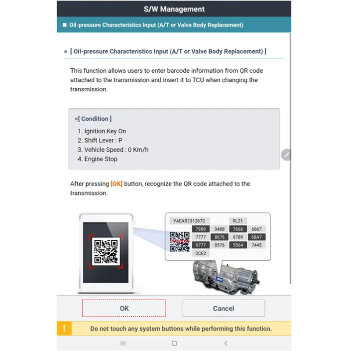
| 6. |
Record the bar code data (oil pressure characteristics) on the automatic
transaxle case or valve body and then input it manually onto the diagnostic
tool.
|
| 7. |
Perform the TCM adaptive values learning procedure.
(Refer to Automatic Transaxle Control System - "Repair procedures")
|
| 8. |
Be sure to check for leaks in each connection part when the engine is
started.
|
Components Location 1. Solenoid valve support bracket 2. Solenoid valve support bracket (Directly solenoid) 3. Line Pressure Control Solenoid Valve 4.
Description • Torque converter control solenoid valve (T/CON_VFS) is attached to the valve body. • This variable force solenoid valve indirectly controls the hydraulic pressure inside the torque converter.
Other information:
Hyundai Santa Fe (TM) 2019-2023 Service and Repair Manual: Windshield Wiper/Washer
Components and components location Component Location 1. Windshield wiper arm & blade 2. Wiper & washer switch 3. Windshield washer hose 4. Windshield wiper motor & linkage 5. Washer motor 6.
Hyundai Santa Fe (TM) 2019-2023 Service and Repair Manual: Rear Corner Radar System
Description and operation Description Rear Corner Radar is a system that measures the relative speed and distance from the following vehicles by using two electromagnetic wave radar sensors attached to the rear bumper, and detects any vehicle within the blind spot zone and gives off alarm.
Categories
- Manuals Home
- Hyundai Santa Fe Owners Manual
- Hyundai Santa Fe Service Manual
- Engine Mechanical System
- Auto Hold. Warning messages
- Front Radar Unit. Repair procedures
- New on site
- Most important about car
