Hyundai Santa Fe (TM): Brake System / Master Cylinder. Repair procedures
| Removal |
| 1. |
Turm ignition switch OFF and disconnect the negative (-) battery cable.
|
| 2. |
Remove the battery.
(Refer to Engine Electrical System - "Battery")
|
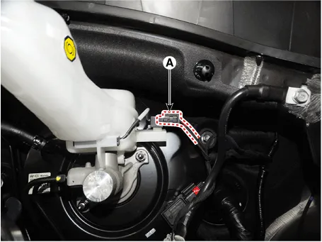
| 3. |
Disconnect the brake fluid level sensor connector (A).
|
| 4. |
Remove the brake fluid from the master cylinder reservoir with a syringe.
|

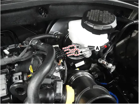
| 5. |
Separate the brake tube (A) from the master cylinder after loosening
the tube flare nut.
|
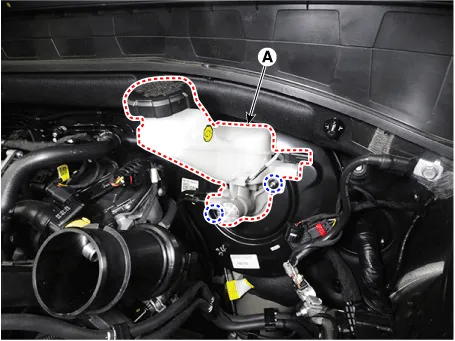
| 6. |
Remove the master cylinder (A) after loosening the master cylinder nuts.
|
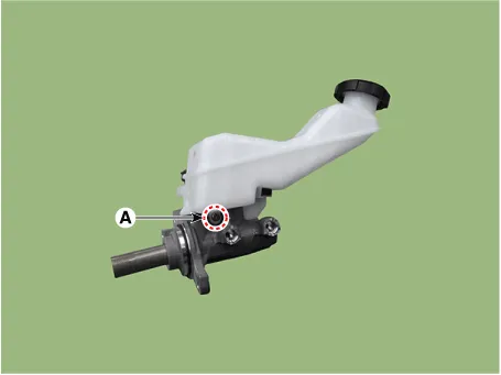
| 7. |
Separate the reservoir from the master cylinder after removing the screw
(A).
|
| Installation |
| 1. |
To install, reverse the removal procedures.
|
| 2. |
After installation, bleed the brake system.
(Refer to Brake System - "Brake System Bleeding")
(Refer to Brake System - "ESP System Bleeding)
|
| 3. |
Check the brake oil leakage and pedal operating condition.
|
Components 1. Reservoir cap 2. Reservoir 3. Reservoir pin 4. Grommet 5. Master cylinder
Removal [G 2.5 T-GDI THETA III (Only)] 1. Disconnect the batter ( - ) cable. 2. Remove the retaining clip then remove the vacuum pump hose (A).
Other information:
Hyundai Santa Fe (TM) 2019-2023 Service and Repair Manual: Seat Electrical
Components and components location Component Location 1. Lumber support motor (Vertical) 2. Lumbar support motor (Horizontal) 3. Reclining motor 4. Rear height motor 5. Front height motor 6. Slide motor 7.
Hyundai Santa Fe (TM) 2019-2023 Service and Repair Manual: Auto Defogging Sensor. Repair procedures
Inspection To inspect and diagnose the sensor, refer to Self-Diagnosis procedure and DTC guide. Replacement 1. Disconnect the negative (-) battery terminal. 2. Remove the rain sensor inner cover (A) and rain sensor cover (B).
Categories
- Manuals Home
- Hyundai Santa Fe Owners Manual
- Hyundai Santa Fe Service Manual
- Parking Brake System. Electronic Parking Brake (EPB)
- 4 Wheel Drive (4WD) System
- Hydraulic System
- New on site
- Most important about car
