Hyundai Santa Fe (TM): Engine Control System / Heated Oxygen Sensor (HO2S). Repair procedures
Hyundai Santa Fe (TM) 2019-2023 Service and Repair Manual / Engine Control/Fuel System / Engine Control System / Heated Oxygen Sensor (HO2S). Repair procedures
| Inspection |
| 1. |
Turn the ignition switch OFF.
|
| 2. |
Disconnect the HO2S connector.
|
| 3. |
Measure resistance between the HO2S terminals 4 and 5 [B1/S1] [Euro-V].
|
| 4. |
Measure resistance between the HO2S terminals 3 and 4 [B1/S1] [Except
Euro-V].
|
| 5. |
Measure resistance between the HO2S terminals 3 and 4 [B1/S2].
|
| 6. |
Check that the resistance is within the specification.
|
| Removal |
| 1. |
Turn the ignition switch OFF and disconnect the battery negative (-)
cable.
|
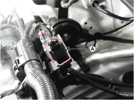
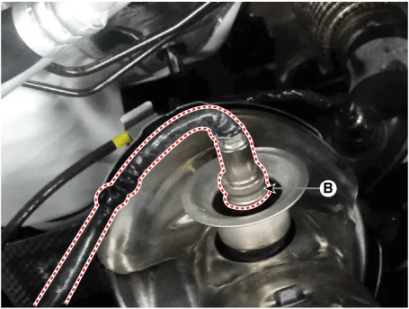
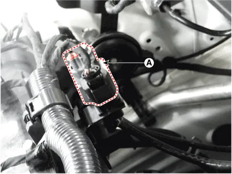
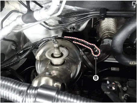
| 2. |
Disconnect the connector (A), and then remove the sensor (B).
[Bank 1 / Sensor 1]
[Bank 1 / Sensor 2]
|

| Installation |
|

|
| 1. |
Installation is reverse of removal.
|
Circuit Diagram Harness Connector [Bank 1 / Sensor 1] [Bank 1 / Sensor 2]
Description On electronic injection systems, there is no longer a load lever that mechanically controls the fuelling. The flow is caculated by the ECM depending on a number of parameters, including pedal position, which is measured using a potentiometer.
Other information:
Hyundai Santa Fe (TM) 2019-2023 Service and Repair Manual: Compressor. Repair procedures
Removal 1. If a compressor is available, the air conditioner is operated for a few minutes in the engine idle state and then the engine is stopped. 2. Disconnect the negative (-) battery terminal.
Hyundai Santa Fe (TM) 2019-2023 Service and Repair Manual: Condenser. Components and components location
Categories
- Manuals Home
- Hyundai Santa Fe Owners Manual
- Hyundai Santa Fe Service Manual
- Blower
- Tire Pressure Monitoring System (TPMS)
- Emission Control System
- New on site
- Most important about car

Copyright © 2026 www.hsafe4.com - 0.0196