Hyundai Santa Fe (TM): Body Electrical System / Head Up Display System
Description and operation
| Description |
| 1. |
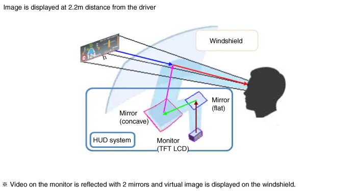
System operation
HUD system displays various information on the windshield glass which
minimizes the driver’s eye movement to enhance safety and convenience.
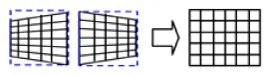
The Head Up Display reflects the TFT LCD images to two mirrors (flat/concave)
and displays them 2.2m ahead from the driver's eye.
Information provided by HUD ;
|
| 2. |
HUD Display Contents
|

| 3. |
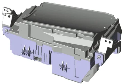
HUD Unit
Head Up Display : Information of the vehicle system is output to the
combine through CAN communication.
|
| 4. |
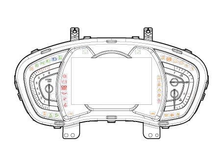
Cluster
|
| 5. |
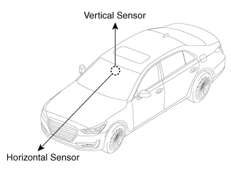
Ambient Light Sensor
Ambient light sensor: The two-direction (horizontal, vertical) measuring
sensor is applied and the HUD brightness is adjusted by the horizontal
measurements.
|

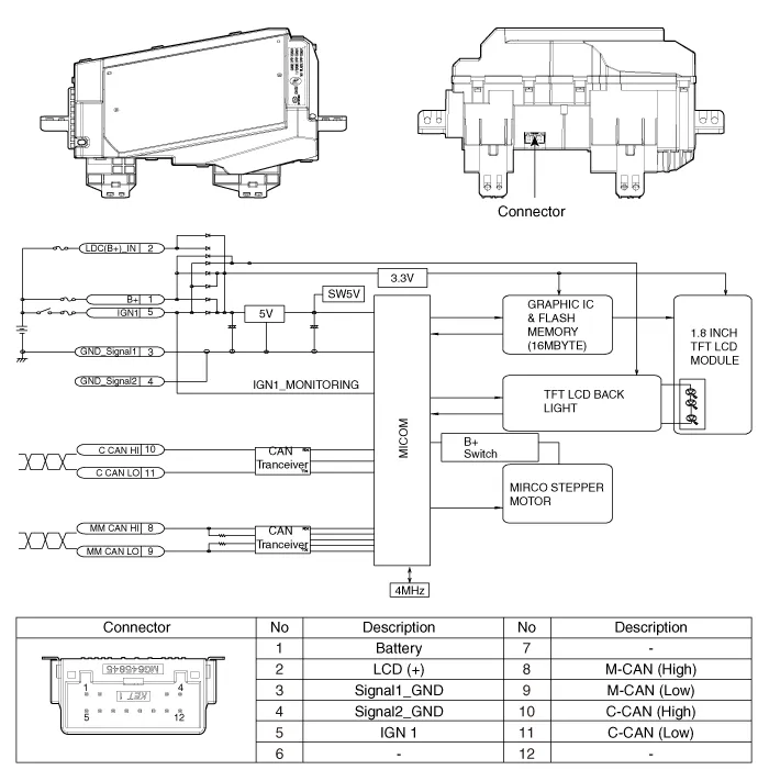
Components and components location
| Components Location |
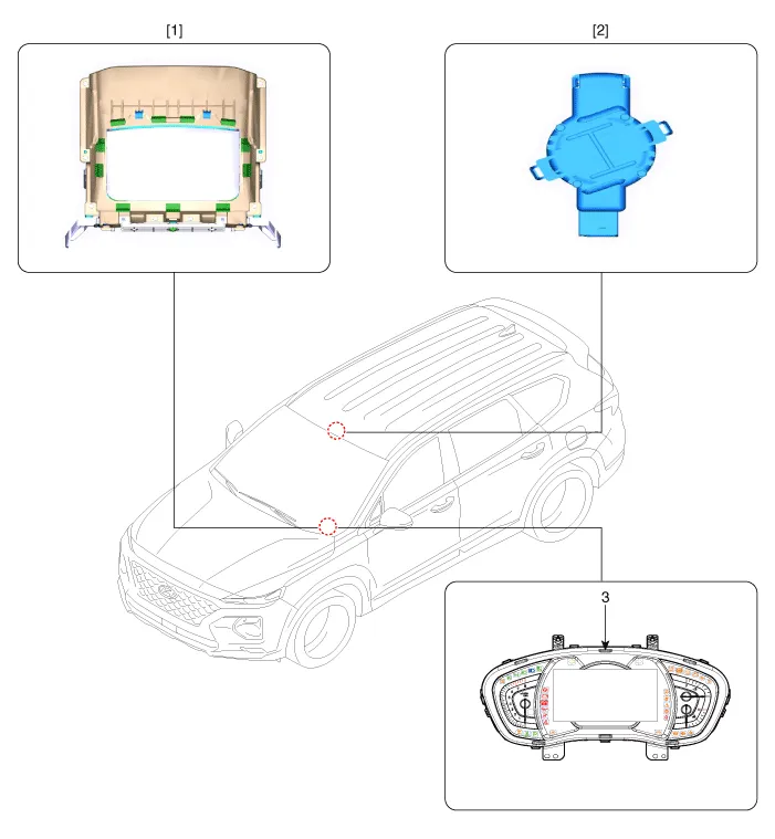
| 1. Head Up Display
(HUD) 2. Rain(Light) sensor |
3. Cluster (User
setting menu On/Off) |
Head Up Display Unit. Components and components location
| Component |
Head Up Display Unit. Troubleshooting
| Troubleshooting |
|
Category |
Error symptoms |
inspection item |
Detailed inspection item |
Related parts |
||||||||||||||
|
Lighting |
|
|
|
Light sensor CGW Cluster |
||||||||||||||
|
Adjustment function |
|
|
|
HUD Cluster |
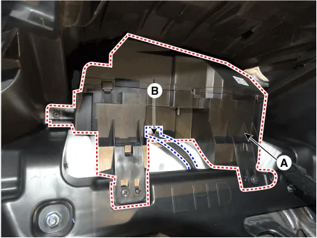
Head Up Display Unit. Repair procedures
| Removal |
| 1. |
Disconnect the negative (-) battery terminal.
|
| 2. |
Remove the instrument cluster.
(Refer to Indicators And Guages - "Instrument Cluster")
|
| 3. |
Remove the head up display unit (A) after disconneting the connector
(B) and loosening the mounting screws.
|
| Installation |
| 1. |
Install the head up display unit.
|
| 2. |
Install the instrument cluster.
|
| 3. |
Connect the negative (-) battery terminal.
|
| Inspection |
| 1. |
In case calibration is required
|
| 2. |
calibration items
|


Components and components location Component Location 1. Head lamp leveling actuator Head Lamp Leveling Switch.
Description and operation Description The system detects the passenger in the vehicle and prevents the driver from getting off the vehicle with the passenger in the back.
Other information:
Hyundai Santa Fe (TM) 2019-2023 Service and Repair Manual: Fuses And Relays
Components and components location Component Location 1. Engine room relay box 2. Sub relay box 3. ICU Junction block 4. ICM relay box Relay Box (Engine Compartment).
Hyundai Santa Fe (TM) 2019-2023 Service and Repair Manual: Auto Defogging Sensor. Repair procedures
Inspection To inspect and diagnose the sensor, refer to Self-Diagnosis procedure and DTC guide. Replacement 1. Disconnect the negative (-) battery terminal. 2. Remove the rain sensor inner cover (A) and rain sensor cover (B).
Categories
- Manuals Home
- Hyundai Santa Fe Owners Manual
- Hyundai Santa Fe Service Manual
- Auto Hold. Warning messages
- Engine Control/Fuel System
- Power Tailgate Module
- New on site
- Most important about car
