Hyundai Santa Fe (TM): Body Electrical System / Fuses And Relays
Components and components location
| Component Location |
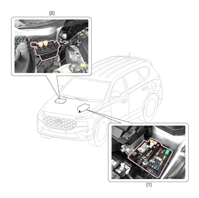
| 1. Engine room
relay box |
2. Sub relay
box |
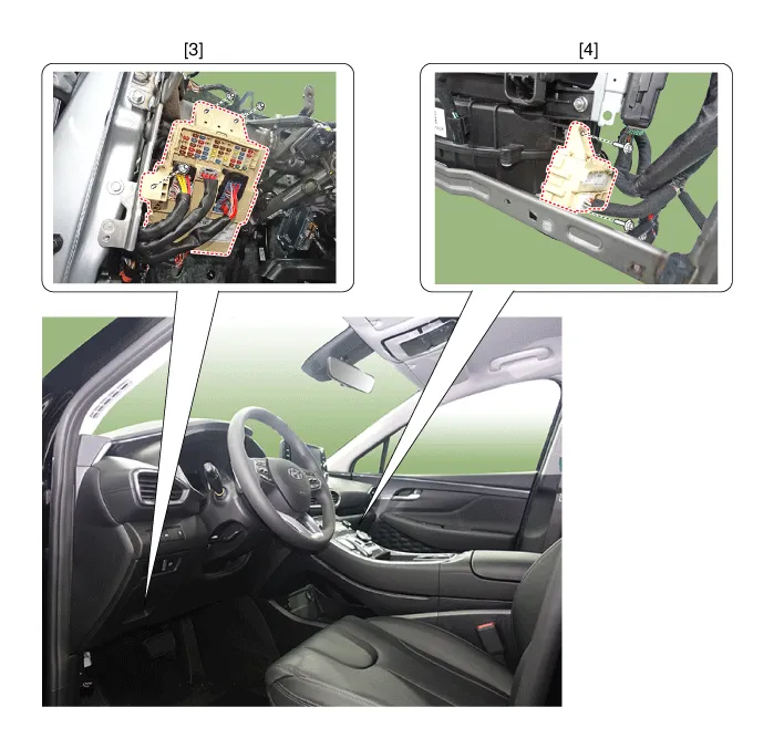
| 3. ICU Junction
block |
4. ICM relay
box |
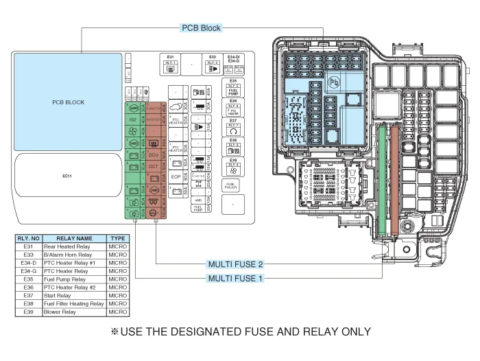
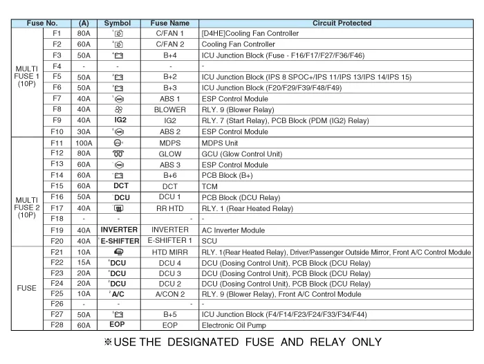
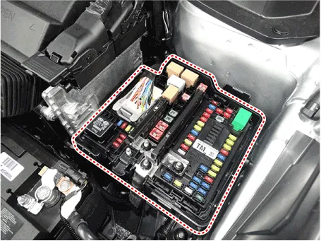
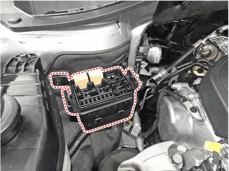
Relay Box (Engine Compartment). Components and components location
| Component Location |
Relay Box (Engine Compartment). Repair procedures
| Inspection |
| 1. |
Disconnect the negative (-) battery terminal.
|
| 2. |
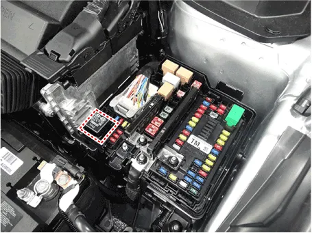
Pull out the relay from the engine compartment relay box.
|
|

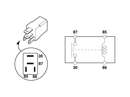
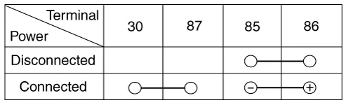
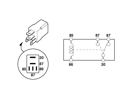
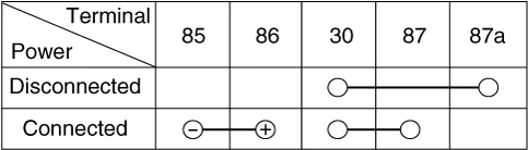
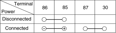
| 1. |
There should be continuity between the No.30 and No.87 terminals when
power and ground are connected to the No.85 and No.86 terminals.
|
| 2. |
There should be no continuity between the No.30 and No.87 terminals
when power is disconnected.
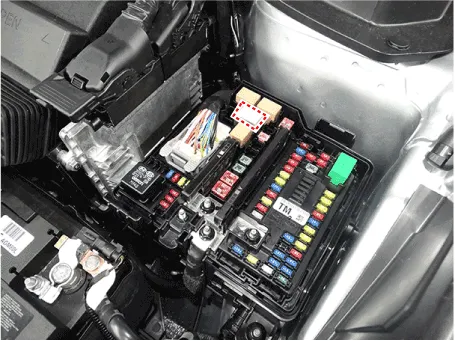
[Engine room relay box]
[Sub junction block]
|
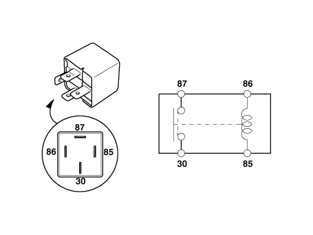
| 1. |
There should be continuity between the No.30 and No.87 terminals when
power and ground are connected to the No.85 and No.86 terminals.
|
| 2. |
There should be continuity between the No.30 and No.87 terminals when
power is disconnected.
|
| 1. |
There should be continuity between the No.30 and No.87 terminals when
power and ground are connected to the No.85 and No.86 terminals.
|
| 2. |
There should be no continuity between the No.30 and No.87 terminals
when power is disconnected.
|
| 1. |
Disconnect the negative (-) battery terminal.
|
| 2. |
Push 4 hooks in the engine room relay box out to the arrow direction
and put up the PCB block (A).
|
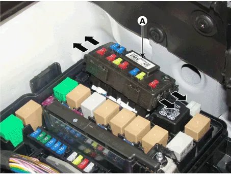
| 3. |
Disconnect the connector and remove the the PCB block (A).
|
| 1. |
Be sure there is no play in the fuse holders, and that the fuses are
held securely.
|
| 2. |
Are the fuse capacities for each circuit correct?
|
| 3. |
Are there any blown fuses?
If a fuse is to be replaced, be sure to use a new fuse of the same capacity.
Always determine why the fuse blew first and completely eliminate the
problem before installing a new fuse.
|
|
Relay Box (Passenger Compartment). Description and operation
| Dscription and Operation |
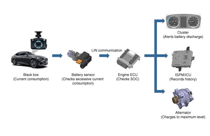
| – |
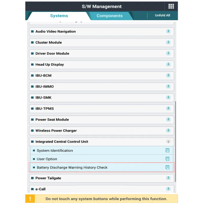
This function allows checking the history of excessive battery consumption
of the parked vehicle.
|
| – |
It is possible to check the running distance and SOC when the battery
consumption was excessive and the current SOC information.
|
| 1. |
Procedure for coding variants
|

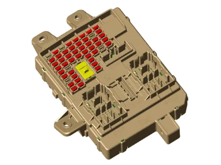
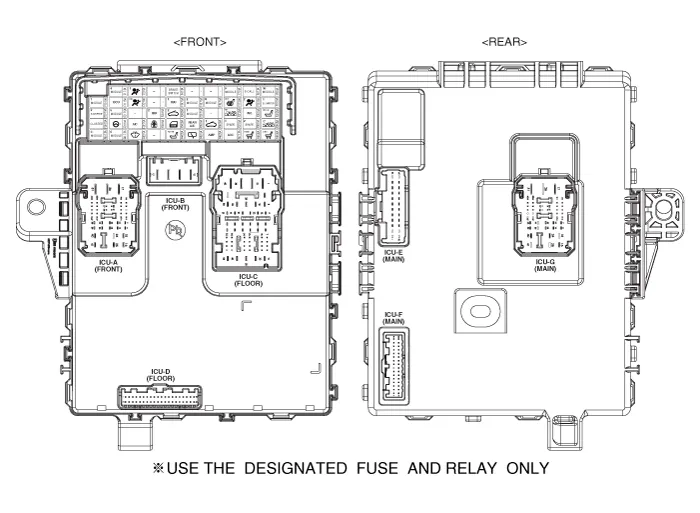
Relay Box (Passenger Compartment). Components and components location
| Components |
Relay Box (Passenger Compartment). Repair procedures
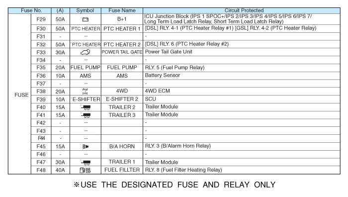
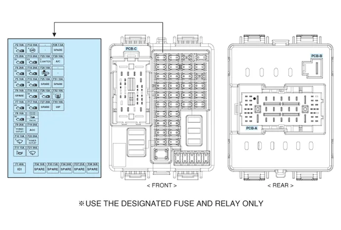
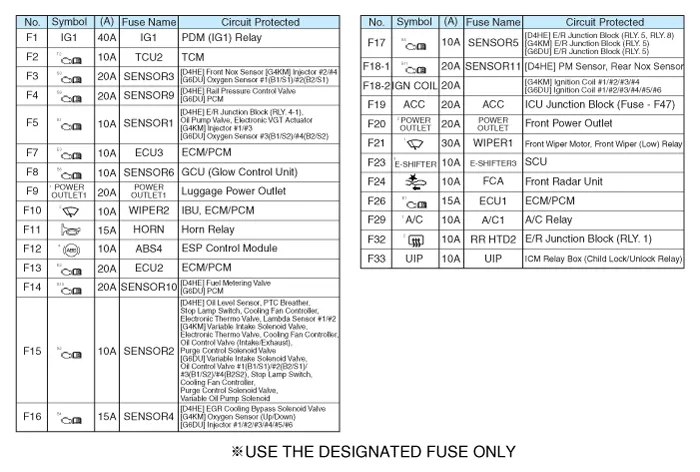
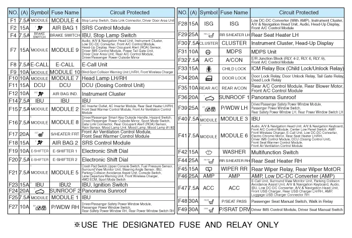
| Fuse Inspection |
| 1. |
Check that the fuse holders are loosely held and that the fuses are
securely fixed by the holders.
|
| 2. |
Check that each fuse circuit has the exact fuse capacity.
|
| 3. |
Check the fuses for any damage.
|
| 1. |
In the body electrical system, failure can be quickly diagnosed by using
the vehicle diagnostic system (diagnostic tool).
The diagnostic system(diagnostic tool) provides the following information.
|
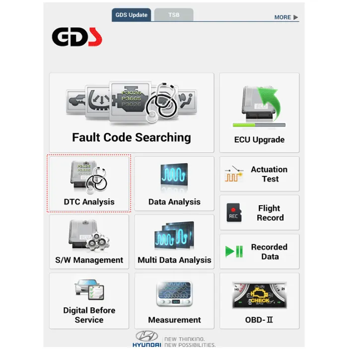
| 2. |
If diagnose the vehicle by diagnostic tool, select "DTC Analysis" and
"Vehicle".
|
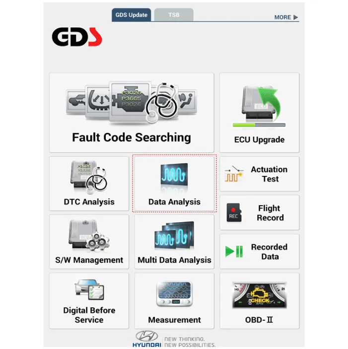
| 3. |
If check current status, select the "Data Analysis" and "Car model".
|
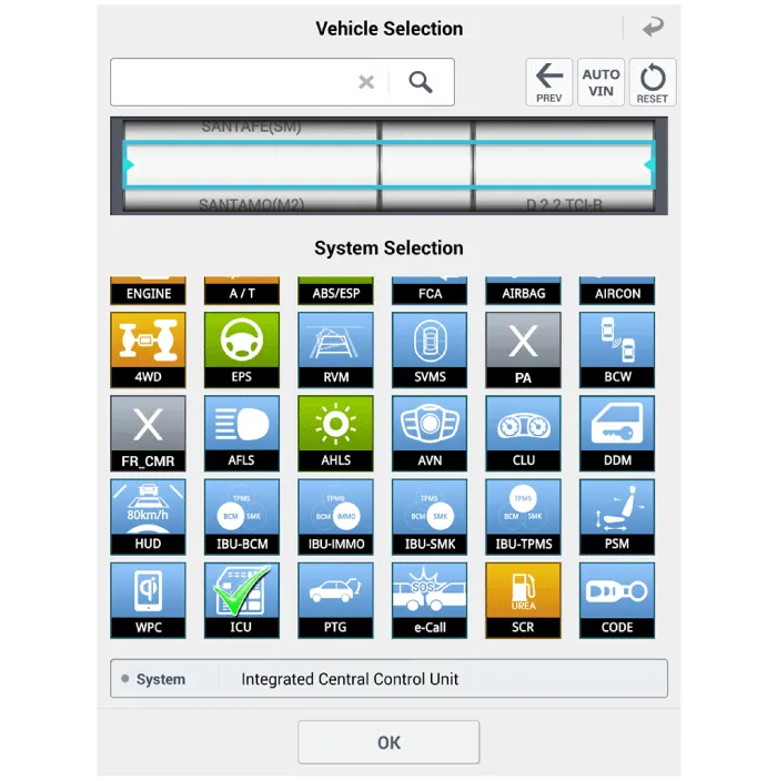
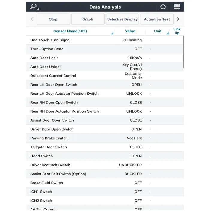
| 4. |
Select the 'ICU' to search the current state of the input/output data.
|
| Removal |
| 1. |
Disconnect the negative (-) battery terminal.
|
| 2. |
Remove the crash pad lower panel.
(Refer to Body - "Crash Pad Lower Panel")
|
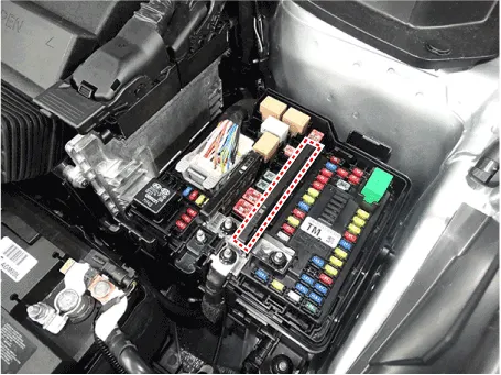
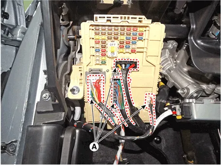
| 3. |
Disconnect the connectors (A) from the fuse side of the ICU.
|
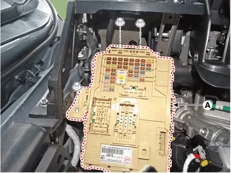
| 4. |
Remove the ICU (A) after loosening the mounting nuts.
|
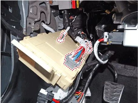
| 5. |
Disconnect the connectors from the back side of the ICU.
|
| Installation |
| 1. |
Install the ICU.
|
| 2. |
Install the crash pad lower panel.
|
| 3. |
Connect the negative (-) battery terminal.
|
| 4. |
Check that all system operates normally.
|
ICM (Integrated Circuit Module) Relay Box. Description and operation
| Description |
ICM (Integrated Circuit Module) Relay Box. Repair procedures
| Inspection |
| 1. |
There should be continuity between the No.15 and No.7,8 terminals when
power and ground are connected to the No.15 and No.14 in the ICM-A.
|
| 2. |
There should be continuity between the No.10 and No.12,13 terminals
when power and ground are connected to the No.15 and No.14 in the ICM-A.
|
| 1. |
There should be continuity between the No.11 and No.12,13 terminals
when power and ground are connected to the No.11 and No.1 in the ICM-A.
|
| 2. |
There should be continuity between the No.10 and No.7,8 terminals when
power and ground are connected to the No.11 and No.11 in the ICM-A.
|
Components and components location Component Location 1. Fuel filler door release actuator Fuel Filler Door Release Actuator.
Troubleshooting Troubleshooting Symptom Possible cause Remedy Speedometer does not operate Cluster fuse (10A) blown Check for short and replace fuse Speedometer faulty Check speedometer CAN line faulty Check the EMS Wiring or ground faulty Repair if necessary Tachometer does not operate Cluster fuse (10A) blown Check for short and replace fuse Tachometer faulty Check tachometer CAN line faulty Check the EMS Wiring or ground faulty Repair if necessary Fuel gauge does not operate Cluster fuse (10A) blown Check for short and replace fuse Fuel gauge faulty Check gauge Fuel sender faulty Check fuel sender Wiring or ground faulty Repair if necessary Low fuel warning lamp does not light up Cluster fuse (10A) blown Check for short and replace fuse Bulb burned out Replace bulb Fuel sender faulty Check fuel sender Wiring or ground faulty Repair if necessary Water temperature gauge does not operate Cluster fuse (10A) blown Check for short and replace fuse Water temperature gauge faulty Check gauge Water temperature sender faulty Check sender CAN line faulty Check the EMS Wiring or ground faulty Repair if necessary Oil pressure warning lamp does not light up Cluster fuse (10A) blown Check for short and replace fuse Bulb burned out Replace bulb Oil pressure switch faulty Check switch Wiring or ground faulty Repair if necessary Parking brake warning lamp does not light up Cluster fuse (10A) blown Check for short and replace fuse Bulb burned out Replace bulb Brake fluid level warning switch faulty Check switch Parking brake switch faulty Check switch Wiring or ground faulty Repair if necessary Open door warning lamp and tailgate warning lamp do not light up Memory fuse (15A) blown Check for short and replace fuse Bulb burned out Replace bulb Door switch faulty Check switch Wiring or ground faulty Repair if necessary Seat belt warning lamp does not light up Cluster fuse (10A) blown Check for short and replace fuse Bulb burned out Replace bulb Seat belt switch faulty Check switch Wiring or ground faulty Repair if necessary Speedometer and odometer does not operate CAN line faulty Check the ABS ECU Wheel speed sensor faulty Check the wheel speed sensor Instrument Cluster.
Other information:
Hyundai Santa Fe (TM) 2019-2023 Service and Repair Manual: Components and components location
Component Location (1) 1. Integrated Body Control Unit (IBU) 2. Buzzer 3. Door outside handle 4. Interior antenna 2 5. Door module antenna 6. Interior antenna 1 Component Location (2) 1.
Hyundai Santa Fe (TM) 2019-2023 Service and Repair Manual: AC Inverter System
Description and operation Description An inverter is a device that transforms the DC voltage from the battery into an AC voltage (220 V). The inverter can power various electrical devices that consume 200 W or less, including mobile phone or notebook rechargers, audio systems, and TVs.
Categories
- Manuals Home
- Hyundai Santa Fe Owners Manual
- Hyundai Santa Fe Service Manual
- Engine Electrical System
- Power Tailgate Module
- Blower
- New on site
- Most important about car
