Hyundai Santa Fe (TM): Brake System / Brake Booster. Repair procedures
| Brake Booster Operating Test |
| 1. |
Run the engine for one or two minutes, and then stop it. If the pedal
depresses fully the first time but gradually becomes higher when depressed
succeeding times, the booster is operating properly, if the pedal height
remains unchanged, the booster is inoperative.
|
| 2. |
With the engine stopped, step on the brake pedal several times.
Then step on the brake pedal and start the engine. If the pedal moves
downward slightly, the booster is in good condition. If there is no
change, the booster is inoperative.
|
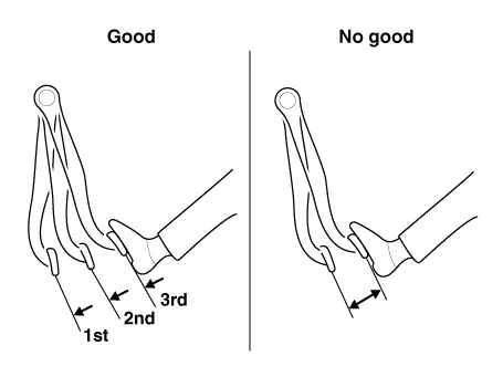
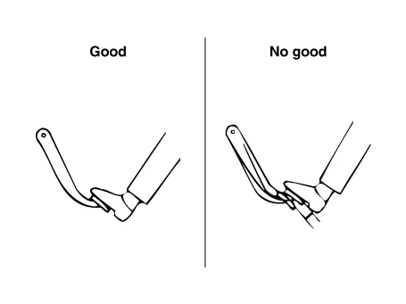
| 3. |
With the engine running, step on the brake pedal and then stop the engine.Hold
the pedal depressed for 30 seconds. If the pedal height does not change,
the booster is in good condition, if the pedal rises, the booster is
inoperative.
If the above three tests are okay, the booster performance can be determined
as good.
Even if one of the above three tests is not okay, check the check valve,
vacuum hose and booster for malfunction.
|
| Removal |
| 1. |
Turn ignition switch OFF and disconnect the negative (-) battery cable.
|
| 2. |
Remove the battery and battery tray.
(Refer to Engine Electrical System - "Battery")
|
| 3. |
Remove the master cylinder.
(Refer to Brake System - "Brake Master Cylinder")
|
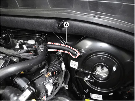
| 4. |
Remove the fixing clip and the vacuum hose (A) from the brake booster.
|
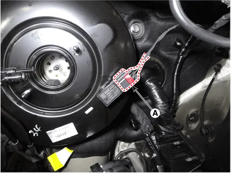
| 5. |
Disconnect the brake booster vacuum pressure sensor connector (A).
|
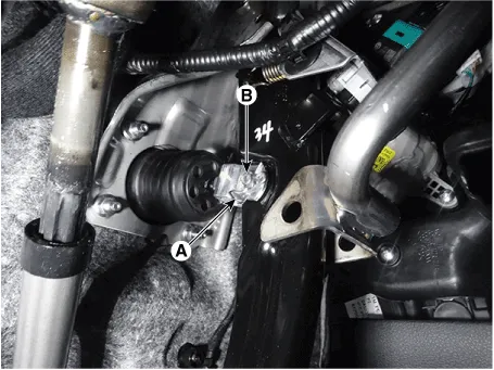
| 6. |
Remove the snap pin (A) and the clevis pin (B).
|
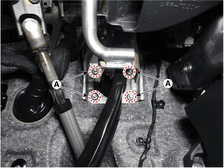
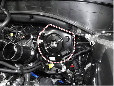
| 7. |
Remove the brake booster (B) after loosening the mounting nuts (A).
|
| Inspection |
| 1. |
Inspect the vacuum hose.
|
| 2. |
Check the boot for damage.
|
| Installation |
| 1. |
To install, reverse the removal procedure.
|

| 2. |
After installation, bleed the brake system.
(Refer to Brake System - "Brake System Bleeding")
(Refer to Brake System - "ESP System Bleeding)
|
| 3. |
Check the brake oil leakage and pedal operating condition.
|
Components 1. Reservoir cap 2. Reservoir 3. Brake booster 4. Master cylinder 5. Push rod
Components 1. Reservoir cap 2. Reservoir 3. Reservoir pin 4. Grommet 5. Master cylinder
Other information:
Hyundai Santa Fe (TM) 2019-2023 Service and Repair Manual: Indicators And Gauges
Troubleshooting Troubleshooting Symptom Possible cause Remedy Speedometer does not operate Cluster fuse (10A) blown Check for short and replace fuse Speedometer faulty Check speedometer CAN line faulty
Hyundai Santa Fe (TM) 2019-2023 Service and Repair Manual: Special service tools
Special Service Tools Tool Name / Number Illustration Description LKA Compensator (09890-3V100) Used for compensating front view camera unit Vertical measuring instrument (09964-C1200) Used to measure l
Categories
- Manuals Home
- Hyundai Santa Fe Owners Manual
- Hyundai Santa Fe Service Manual
- 4 Wheel Drive (4WD) System
- Rear seats
- Blower
- New on site
- Most important about car
