Hyundai Santa Fe (TM): Engine Control System / Accelerator Position Sensor (APS). Schematic diagrams
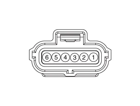
| Circuit Diagram |
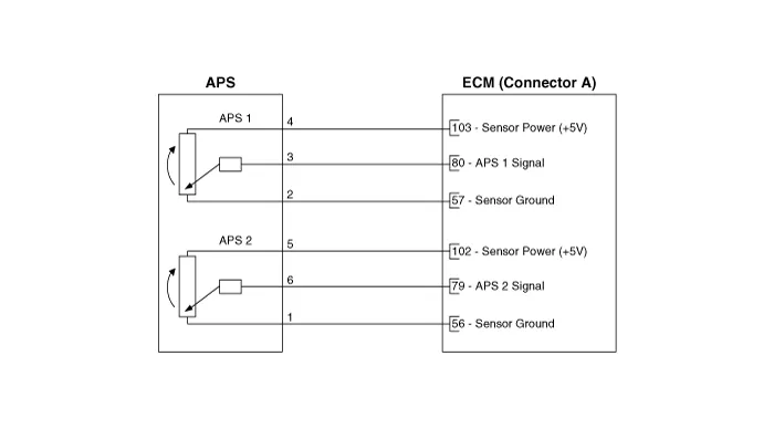
Specification Accelerator Position Output Voltage (V) [Vref=5V] APS 1 APS 2 C.
Inspection 1. Connect the diagnostic tool on the Data Link Connector (DLC). 2. Turn the ignition switch ON.
Other information:
Hyundai Santa Fe (TM) 2019-2023 Service and Repair Manual: Fuel Filler Door
Components and components location Component Location 1. Fuel filler door release actuator Fuel Filler Door Release Actuator. Repair procedures Removal 1. Remove the left luggage side trim.
Hyundai Santa Fe (TM) 2019-2023 Service and Repair Manual: Button Engine Start System
Description and operation Description System Overview The System offers the following features: – Changing the state of engine ignition and power by using the start button. – Controlling external relays for ACC / IGN1 / IGN2 terminal switching and STARTER, without use
Categories
- Manuals Home
- Hyundai Santa Fe Owners Manual
- Hyundai Santa Fe Service Manual
- Automatic Transaxle Control System
- Parking Brake System. Electronic Parking Brake (EPB)
- Engine Mechanical System
- New on site
- Most important about car
