Hyundai Santa Fe (TM): Engine Control System / Accelerator Position Sensor (APS). Specifications
| Specification |
|
Accelerator Position |
Output Voltage (V) [Vref=5V] |
|
|
APS 1 |
APS 2 |
|
|
C.T |
0.7 - 0.8 |
0.33 - 0.43 |
|
W.O.T |
3.98 - 4.35 |
1.93 - 2.17 |
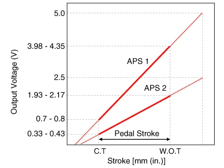
Description On electronic injection systems, there is no longer a load lever that mechanically controls the fuelling. The flow is caculated by the ECM depending on a number of parameters, including pedal position, which is measured using a potentiometer.
Circuit Diagram Harness Connector
Other information:
Hyundai Santa Fe (TM) 2019-2023 Service and Repair Manual: General safety information and caution
Instructions (R-134a) When Handling Refrigerant 1. R-134a liquid refrigerant is highly volatile. A drop on the skin of your hand could result in localized frostbite. When handling the refrigerant, be sure to wear gloves.
Hyundai Santa Fe (TM) 2019-2023 Service and Repair Manual: Front Radar Unit. Repair procedures
Inspection Inspection procedure for vehicle with Forward Collision-Avoidance Assist and Smart Cruise Control system failure 1. Check the bumper appearance for accident (check the vehicle appearance visually and see bumper replacement history).
Categories
- Manuals Home
- Hyundai Santa Fe Owners Manual
- Hyundai Santa Fe Service Manual
- Engine Electrical System
- Automatic Transaxle Control System
- Engine Control/Fuel System
- New on site
- Most important about car
