Hyundai Santa Fe (TM): Engine Control System / Accelerator Position Sensor (APS). Repair procedures
| Inspection |
| 1. |
Connect the diagnostic tool on the Data Link Connector (DLC).
|
| 2. |
Turn the ignition switch ON.
|
| 3. |
Measure the output voltage of the APS 1 and 2 at C.T and W.O.T.
|
|||||||||||
| Removal |
| 1. |
Turn the ignition switch OFF and disconnect the battery (-) terminal.
|
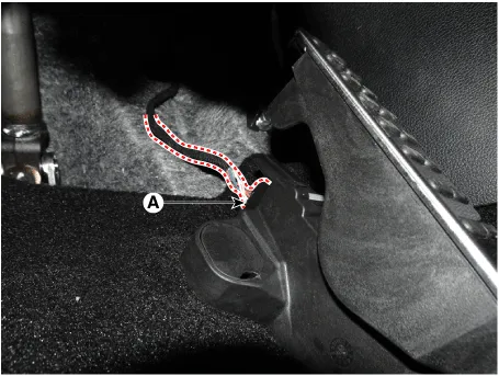
| 2. |
Disconnect the accelerator position snesor connector (A).
|
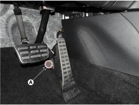
| 3. |
Disconnect the mounting cap (A).
|
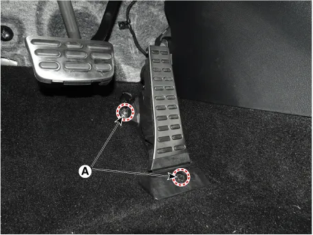
| 4. |
Remove the accelerator pedal module from the vehicle after loosening
the mounting bolt (A).
|
| Installation |
| 1. |
Install in the reverse order of removal.
|
Circuit Diagram Harness Connector
Description Based on information from various sensors, the ECM can calculate the fuel amount to be injected. The fuel injector is a solenoid-operated valve and the fuel injection amount is controlled by length of injection time.
Other information:
Hyundai Santa Fe (TM) 2019-2023 Service and Repair Manual: Specifications
Specifications Smart Key Unit Items Specification Rated voltage DC 12V Operating voltage DC 9 - 16V Operating temperature -22°F to 167°F (-30°C to- 75°C) Load Max.
Hyundai Santa Fe (TM) 2019-2023 Service and Repair Manual: Keyless Entry And Burglar Alarm
Description and operation Description Burglar Alarm State [B/A State] B/A State Description DISARM 1) In "DISARM" state, no vehicle start inhibition.
Categories
- Manuals Home
- Hyundai Santa Fe Owners Manual
- Hyundai Santa Fe Service Manual
- Auto Hold. Warning messages
- Vehicle auto-shut off. System Operation
- Engine Electrical System
- New on site
- Most important about car
