Hyundai Santa Fe (TM): Motor Driven Power Steering / Steering Column and Shaft. Repair procedures
| Removal |
| 1. |
Turn the ignition switch OFF and disconnect the battery negative (-)
cable.
|
| 2. |
Turn the steering wheel so that the front wheels are placed in the straight
ahead position.
|
| 3. |
Remove the driver airbag module.
(Refer to Restraint - "Driver Airbag (DAB) Module and Clock Spring")
|
| 4. |
Remove the steering wheel.
(Referto Steering System - "Steering Wheel")
|
| 5. |
Remove the clock spring.
(Refer to Restraint - "Driver Airbag (DAB) Module and Clock Spring")
|
| 6. |
Remove the multifunction switch.
(Refer to Body Electrical System - "Multifunction switch")
|
| 7. |
Remove the steering column shroud lower panel
(Refer to Body - "Steering Column Shroud lower Panel")
|
| 8. |
Remove the crash pad lower pannel.
(Refer to Body - "Crash Pad Lower Pannel")
|
| 9. |
Disconnect the MDPS connector (A).
|

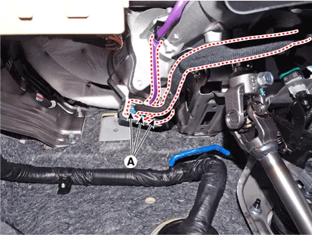
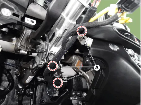
| 10. |
Remove the fixed clip (A) and then remove the wiring from the steering
column.
|
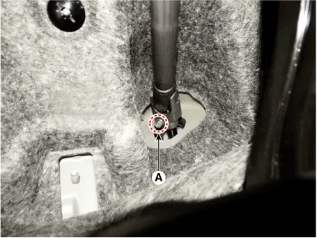
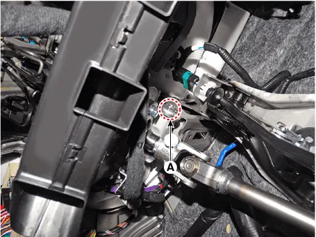
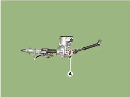
| 11. |
Loosen the bolt (A) and then disconnect the universal joint assembly
from the pinion of the steering gear box.
|

| 12. |
Remove the stop lamp switch.
(Refer to Brake System - "Stop Lamp Switch")
|
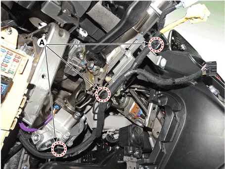
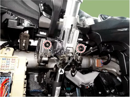
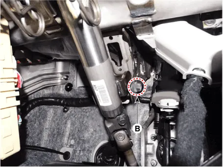
| 13. |
Remove the MDPS assembly by loosening the mounting nuts (A) and bolt
(B).
|

| 14. |
Install in the reverser order of removal.
|
| 15. |
Conduct the "EPS Type Recognition" by diagnostic tool.
(Refer to MDPS motor - "Diagnosis with diagnostic tool")
|
| 16. |
Conduct the "ASP Calibration" by diagnostic tool.
(Refer to MDPS motor - "Diagnosis with diagnostic tool")
|
| 1. |
Turn the steering wheel so that the front wheels are placed in the straight
ahead position.
|
| 2. |
Turn the ignition switch OFF and disconnect the battery negative (-)
cable.
|
| 3. |
Remove the driver airbag module.
(Refer to Restraint - "Driver Airbag (DAB) Module and Clock Spring")
|
| 4. |
Remove the steering wheel.
(Referto Steering System - "Steering Wheel")
|
| 5. |
Remove the clock spring.
(Refer to Restraint - "Driver Airbag (DAB) Module and Clock Spring")
|
| 6. |
Remove the multifunction switch.
(Refer to Body Electrical System - "Multifunction switch")
|
| 7. |
Remove the steering column shroud lower panel
(Refer to Body - "Steering Column Shroud lower Panel")
|
| 8. |
Remove the crash pad lower pannel.
(Refer to Body - "Crash Pad Lower Pannel")
|
| 9. |
Remove the fixing clip (A) from the steering column.
|
| 10. |
Loosen the bolt (A) and then disconnect the universal joint assembly
from the pinion of the steering gear box.
|
| 11. |
Remove the stop lamp switch.
(Refer to Brake System - "Stop Lamp Switch")
|
| 12. |
Remove the MDPS assembly by loosening the mounting nuts (A) and bolt
(B).
|
| Disassembly |
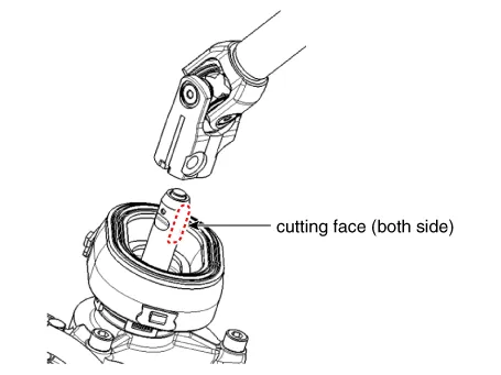
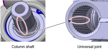
| 1. |
Loosen the bolt (A) and then disconnect the universal joint assembly
from the steering column assembly.
|
| 2. |
Reassembly is the reverse of the disassembly.
|
| Inspection |
| 1. |
Check the steering column for damage and deformation.
|
| 2. |
Check the steering column for damage and deformation.
|
| 3. |
Check the join bearing for damage and wear.
|
| 4. |
Check the tilt bracket for damage and cracks.
|
| 5. |
Check the key lock assembly for proper operation and replace it if necessary.
|
| Diagnosis with diagnostic tool |
| EPS Type Recognition |
|
| 1. |
Connect self-diagnosis connector(16pins) located in the lower of driver
side crash pad to self-diagnosis device.
|
| 2. |
Turn the self-diagnosis device after key is ON.
|
| 3. |
Turn the steering wheel to straight ahead position.
|
| 4. |
After Selecting the "vehicle model" and "system", select the "EPS Type
Recognition" on diagnostic tool vehicle selection screen.
|

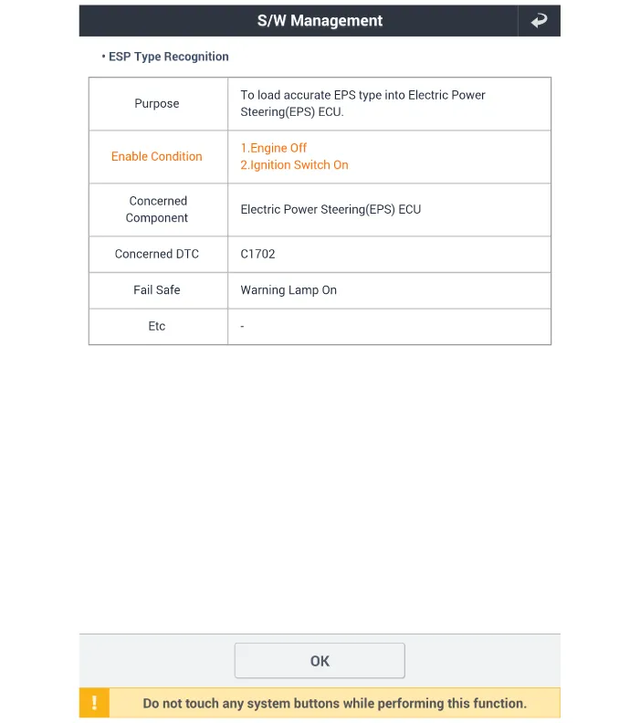
| 5. |
Remove the DTC.
|
| 6. |
Turn off the IG switch and wait for 20 seconds or more before starting
the engine. And then make sure that MDPS works properly.
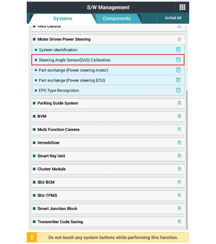
SAS Calibration
|
| 1. |
Connect self - diagnosis connector (16pins) located in the lower of
driver side crash pad to self - diagnosis device.
|
| 2. |
Turn the self - diagnosis device after key is ON.
|
| 3. |
Turn the steering wheel to straight ahead position.
|
| 4. |
After Selecting the "vehicle model" and "system", select the "SAS Calibration"
on diagnostic tool vehicle selection screen.
|
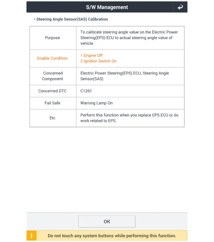
| 5. |
Remove the DTC.
|
| 6. |
Turn off the IG switch and wait for 10 seconds or more before starting
the engine. And then make sure that MDPS works properly.
|
| Installation |
| 1. |
To install, reverse the removal procedures.
|
| 2. |
Check the alignment.
(Refer to Suspension System - "Alingment")
|
Replacement 1. Turn the ignition switch OFF and disconnect the battery negative (-) cable. 2.
Components [R-MDPS] 1. Tie rod end 2. Lead wire 3. Short gear 4. Power pack [C-MDPS] 1.
Other information:
Hyundai Santa Fe (TM) 2019-2023 Service and Repair Manual: Compressor. Components and components location
Components [Diesel 2.2 TCI-R] 1. Clutch Bolt 2. Disc & Hub Assembly 3. Clutch Spacer 4. Snap Ring 5. Pulley 6. Magnetic Coil Assembly 7. Compressor 8. Electric Control Valve (ECV) spacer 9.
Hyundai Santa Fe (TM) 2019-2023 Service and Repair Manual: In-car Sensor. Description and operation
Description The In-car air temperature sensor is built in the heater & A/C control unit. The sensor consists of a thermistor that measures the inside temperature. The signal decided by the resistance value that changes in accordance with perceived inside temperature, is delivered to heater control unit, and according t
Categories
- Manuals Home
- Hyundai Santa Fe Owners Manual
- Hyundai Santa Fe Service Manual
- Tire Pressure Monitoring System (TPMS)
- Engine Mechanical System
- Gauges and meters
- New on site
- Most important about car
