Hyundai Santa Fe (TM): Integrated Body Control Unit (IBU) / Repair procedures
| Removal |
| 1. |
Disconnect the negative (-) battery terminal.
|
| 2. |
Remove the glove box.
(Refer to Body - "Glove Box")
|
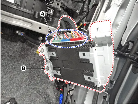
| 3. |
Disconnect the body control module connectors (A) and then remove the
integrated body control unit (B).
|
| Installation |
| 1. |
Install the integrated body control module.
|
| 2. |
Connect the integrated body control module.
|
| 3. |
Install the glove box.
|
| IBU Diagnosis With Diagnostic Tool |
| 1. |
In the body electrical system, failure can be quickly diagnosed by using
the vehicle diagnostic system.
|
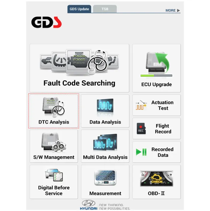
| 2. |
If diagnose the vehicle by diagnostic tool, select "DTC Analysis" and
"Vehicle".
|
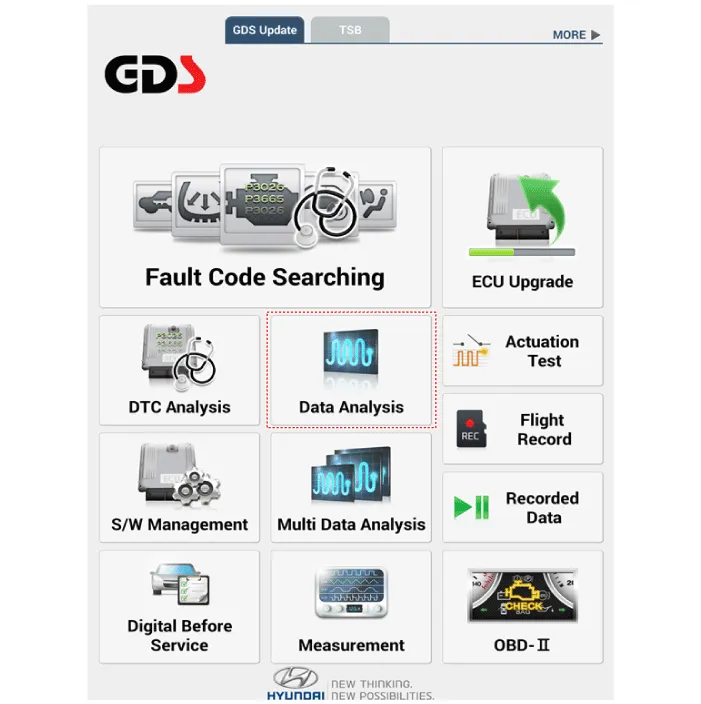
| 3. |
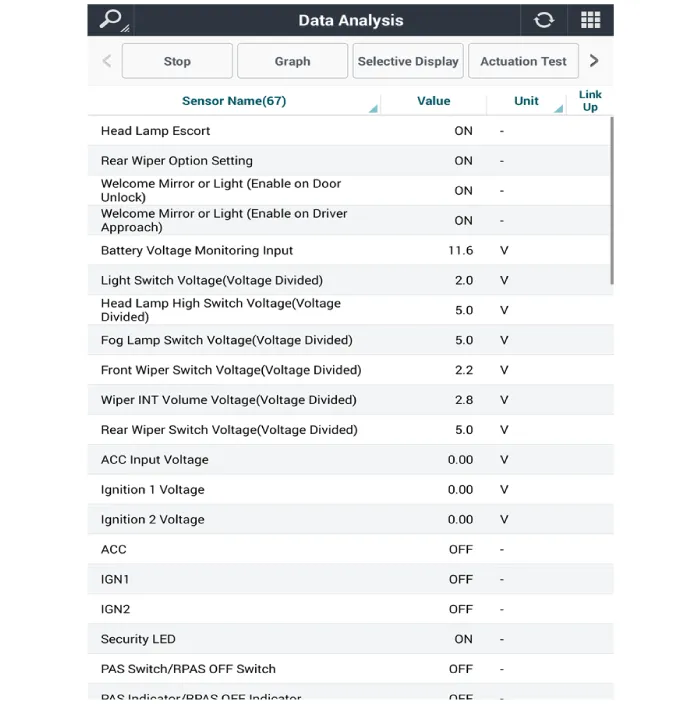
If check current status, select the "Data Analysis" and "Car model".
|
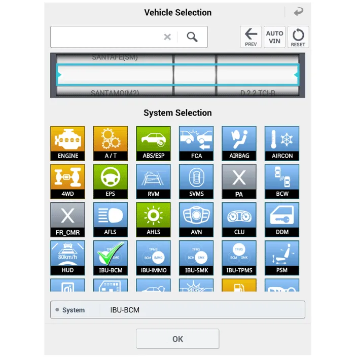
| 4. |
Select the 'IBU_BCM' to search the current state of the input/output
data.
|
Circuit Diagram With Smart Key Without Smart Key
Other information:
Hyundai Santa Fe (TM) 2019-2023 Service and Repair Manual: Mode Control Actuator. Repair procedures
Inspection 1. Turn the ignition switch OFF. 2. Disconnect the mode control actuator connector. 3. Verify that the mode control actuator operates to the defrost mode when connecting 12V to terminal 3 and grounding terminal 7.
Hyundai Santa Fe (TM) 2019-2023 Service and Repair Manual: Specifications
Specifications [ADAS_PRK Application Specification (MOBIS)] Item Specification Ultrasonic sensor Voltage rating DC 12V Detecting range 40cm ~ 120cm Operating voltage DC 9V ~ 16V Operation curr
Categories
- Manuals Home
- Hyundai Santa Fe Owners Manual
- Hyundai Santa Fe Service Manual
- Engine Control/Fuel System
- Convenience features
- Suspension System
- New on site
- Most important about car

Copyright © 2025 www.hsafe4.com - 0.0216