Hyundai Santa Fe (TM): Engine Mechanical System / Cylinder Head Assembly
Hyundai Santa Fe (TM) 2019-2023 Service and Repair Manual / Engine Mechanical System / Cylinder Head Assembly
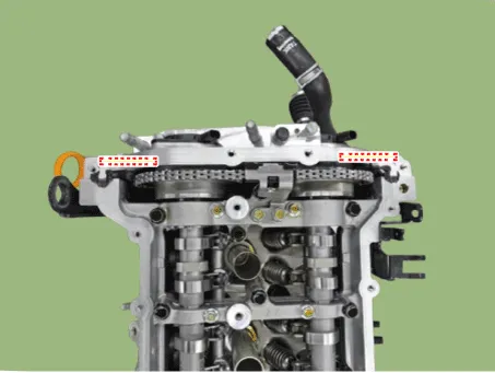
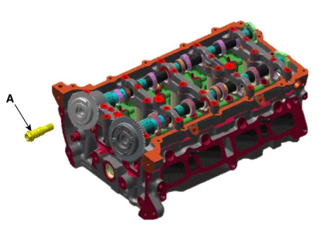
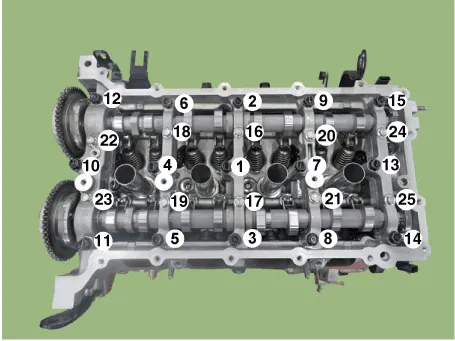
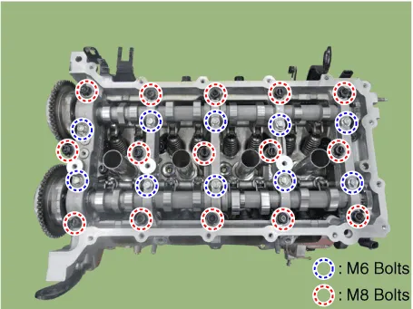
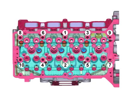
Components and components location
| Components |
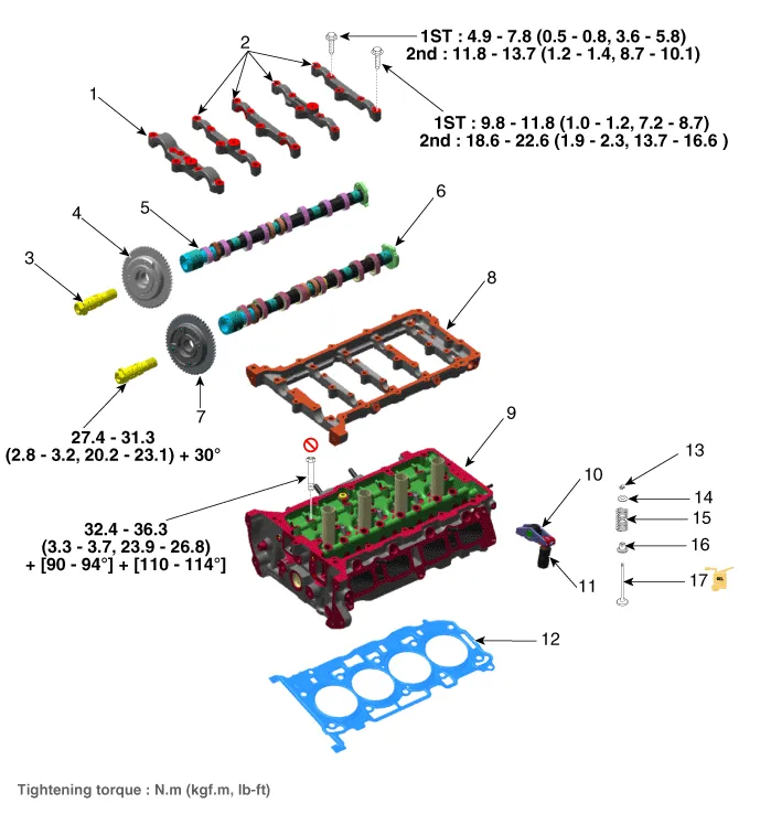
| 1. Camshaft
front bearing cap 2. Camshaft bearing cap 3. OCV & Center bolt 4. Exhaust CVVT assembly 5. Exhaust camshaft 6. Intake camshaft |
7. Intake
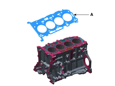
CVVT assembly 8. Cam carrier 9. Cylinder head 10. Swing arm 11. Hydraulic lash adjuster (HLA) 12. Cylinder head gasket |
13. Retainer
lock 14. Retainer 15. Valve spring 16. Valve stem seal 17. Valve |
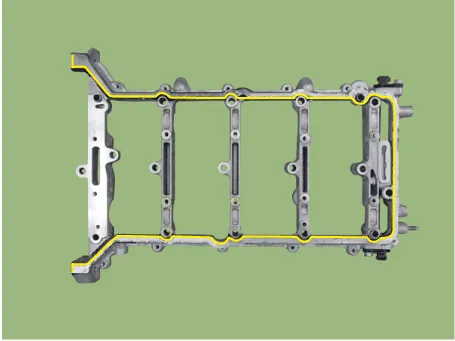
Cylinder Head Cover. Components and components location
| Components |
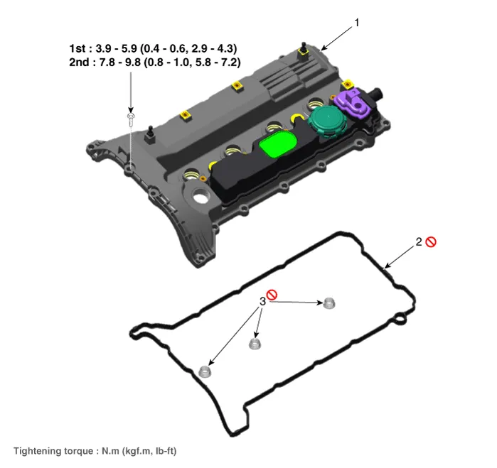
| 1. Cylinder head
cover 2. Cylinder head cover gasket |
3. Cylinder head
cover center bolt gasket |
Cylinder Head Cover. Repair procedures
| Removal |
| 1. |
Disconnect the battery negative terminal.
|
| 2. |
Remove the engine cover.
|

| 3. |
Disconnect the wiring connectors and harness clamps and remove the connector
brackets around the cylinder head cover.
|
| 4. |
Remove the ignition coils.
(Refer to Engine Electrical System - "Ignition Coil")
|
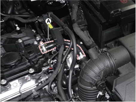
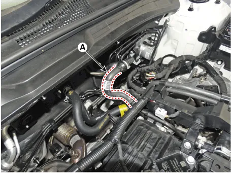
| 5. |
Disconnect the breather hose (A).
|
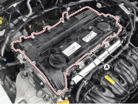
| 6. |
Remove the cylinder head cover (A).
|
| Installation |
| 1. |
Install cylinder head cover.
|

| 2. |
Connect the breather hose (A).
|
| 3. |
Install the ignition coils.
(Refer to Engine Electrical System - "Ignition Coil")
|
| 4. |
Connect the wiring connectors and harness clamps and remove the connector
brackets around the cylinder head cover.
|
| 5. |
Installation is in the reverse order of removal.
|
CVVT & Camshaft. Description and operation
| Description |
Continuous Variable Valve Timing (CVVT) system advances or retards the valve
timing of the intake and exhaust valve in accordance with the ECM control signal
which is calculated by the engine speed and load.
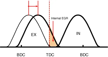
By controlling CVVT, the valve over-lap or under-lap occurs, which makes better
fuel economy and reduces exhaust gases (NOx, HC) and improves engine performance
through reduction of pumping loss, internal EGR effect, improvement of combustion
stability, improvement of volumetric efficiency, and increase of expansion work.
This system consist of
| – |
the CVVT Oil Control Valve (OCV) which supplies the engine oil to the
cam phaser or runs out the engine oil from the cam phaser in accordance
with the ECM PWM (Pulse With Modulation) control signal,
|
| – |
and the Cam Phaser which varies the cam phase by using the hydraulic
force of the engine oil.
|
The engine oil getting out of the CVVT oil control valve varies the cam phase
in the direction (Intake Advance/Exhaust Retard) or opposite direction (Intake
Retard/Exhaust Advance) of the engine rotation by rotating the rotor connected
with the camshaft inside the cam phaser.

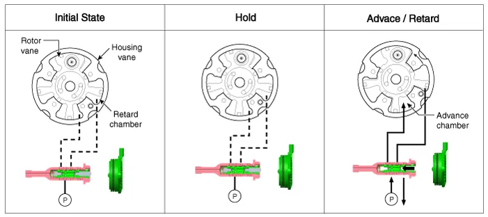
| Operation Principle |
The CVVT has the mechanism rotating the rotor vane with hydraulic force generated
by the engine oil supplied to the advance or retard chamber in accordance with
the CVVT oil control valve control.
|

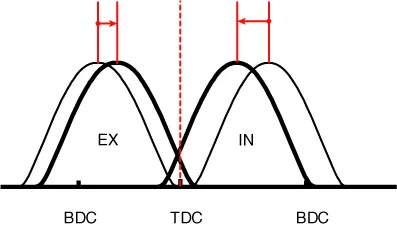
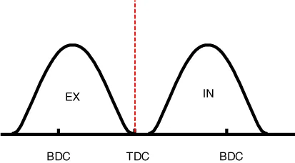
| [CVVT System Mode] |
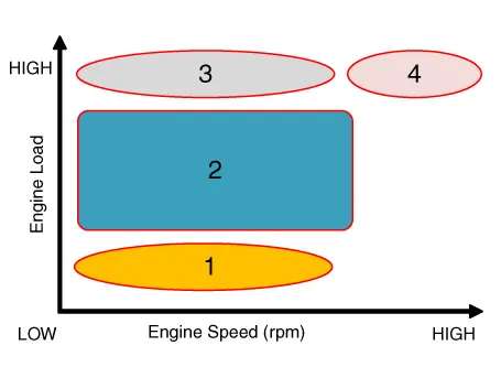
|
(1) Low Speed / Low Load |
(2) Part Load |
|
|
|
|
(3) Low Speed / High Load |
(4) High Speed / High Load |
|
|
|
|
Driving Condition |
Exhaust Valve |
Intake Valve |
||
|
Valve Timing |
Effect |
Valve Timing |
Effect |
|
|
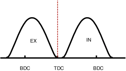
(1) Low Speed /Low Load |
Completely Advance |
* Valve Under-lap * Improvement of combustion stability |
Completely Retard |
* Valve Under-lap * Improvement of combustion stability |
|
(2) Part Load |
Retard |
* Increase of expansion work * Reduction of pumping loss * Reduction of HC |
Retard |
* Reduction of pumping loss |
|
(3) Low Speed /High Load |
Retard |
* Increase of expansion work |
Advance |
* Prevention of intake back flow (Improvement of volumetric efficiency) |
|
(4) High Speed /High Load |
Advance |
* Reduction of pumping loss |
Retard |
* Improvement of volumetric efficiency |
CVVT & Camshaft. Repair procedures
| Removal |
|

CVVT & Cam Shaft
| 1. |
Remove the timing chain.
(Refer to Timing System - "Timing Chain")
|
| 2. |
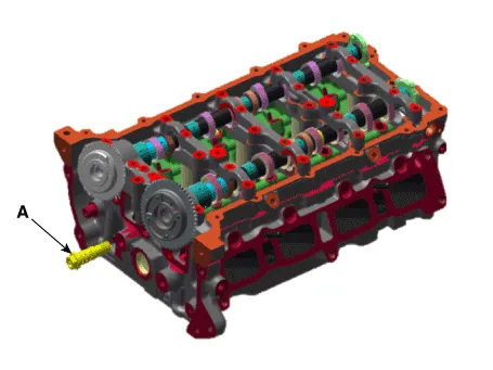
Remove the oil control valve (OCV) and center bolt (A).
[Intake oil control valve (OCV) and Center Bolt]
[Exhaust oil control valve (OCV) and Center Bolt]
|
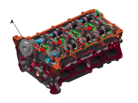
| 3. |
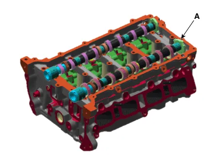
Remove the intake CVVT (A).
|
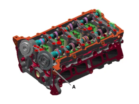
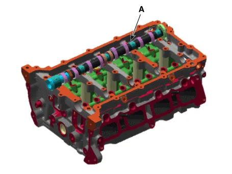
| 4. |
Remove the exhaust CVVT (A).
|
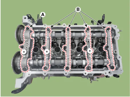
| 5. |
Remove the camshaft front bearing cap (A) and camshaft bearing caps
(B).
|
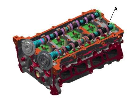
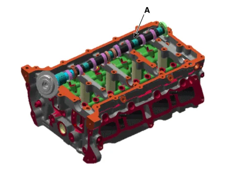
| 6. |
Remove the camshaft (A).
[Intake Camshaft]
[Exhaust Camshaft]
|
CVVT & Cam Shaft Assembly
| 1. |
Remove the timing chain.
(Refer to Timing System - "Timing Chain")
|
| 2. |
Remove the camshaft front bearing cap (A) and camshaft bearing caps
(B).
|
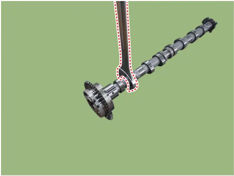
| 3. |
Remove the intake camshaft & CVVT assembly (A).
|
| 4. |
Remove the exhaust camshaft & CVVT assembly (A).
|
| Inspection |
Camshaft
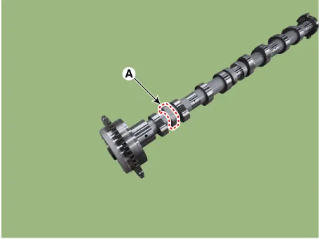
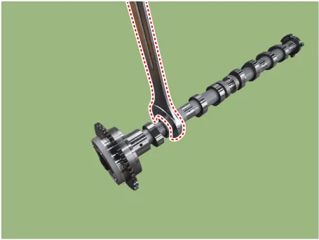
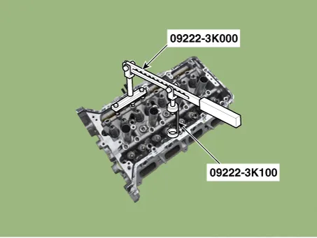
| 1. |
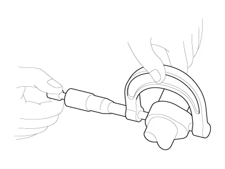
Inspect the cam lobes.
Using a micrometer, measure the cam lobe height.
If the cam lobe height is less than standard, replace the camshaft.
|
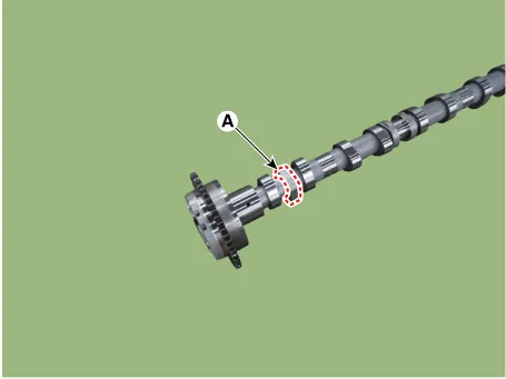
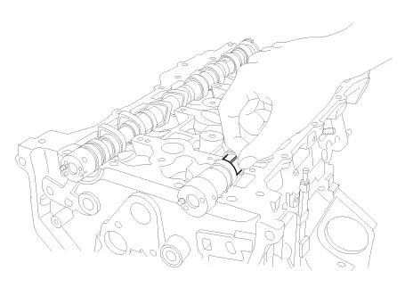
| 2. |
Inspect the camshaft journal clearance.
|

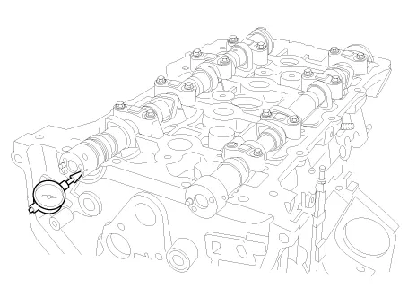
| 3. |
Inspect the camshaft end play.
|
| Installation |
CVVT & Cam Shaft
| 1. |
Install the camshaft (A).
[Intake Camshaft]
[Exhaust Camshaft]
|
| 2. |
Install the camshaft front bearing cap (A) and camshaft bearing caps
(B).
|
| 3. |
Install the exhaust CVVT (A).
|
| 4. |
Install the intake CVVT (A).
|
| 5. |
Install the oil control valve (OCV) and center bolt (A).
[Intake oil control valve (OCV) and Center Bolt]
[Exhaust oil control valve (OCV) and Center Bolt]
|
| 6. |
Install the timing chain.
(Refer to Timing System - "Timing Chain")
|
CVVT & Cam Shaft Assembly
| 1. |
Install the exhaust camshaft & CVVT assembly (A).
|
| 2. |
Install the intake camshaft & CVVT assembly (A).
|
| 3. |
Install the camshaft front bearing cap (A) and camshaft bearing caps
(B).
|
| 4. |
Install the timing chain.
(Refer to Timing System - "Timing Chain")
|
Cylinder Head. Repair procedures
| Removal |
|
|
|
| 1. |
Disconnect the battery negative terminal.
|
| 2. |
Remove the engine cover.
(Refer to Engine and Transaxle Assembly - "Engine Cover")
|
| 3. |
Remove the engine room under cover.
(Refer to Engine and Transaxle Assembly - "Engine Room Under Cover")
|
| 4. |
Drain the coolant.
(Refer to Cooling System - "Coolant")
|
| 5. |
Drain the engine oil.
(Refer to Lubrication System - "Engine Oil")
|
| 6. |
Remove the air duct and air cleaner assembly.
(Refer to Intake and Exhaust System - "Air Cleaner")
|
| 7. |
Remove the battery tray.
(Refer to Engine Electrical System - "Battery")
|
| 8. |
Disconnect the radiator upper hose (A).
|

| 9. |
Disconnect the brake vacuum hose (A).
|
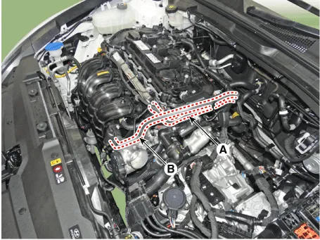
| 10. |
Disconnect the fuel hose (A) and purge control solenoid valve (PCSV)
hose (B).
|
| 11. |
Remove the delivery pipe.
(Refer to Engine Control / Fuel System - "Delivery Pipe")
|
| 12. |
Remove the intake manifold.
(Refer to Intake and Exhaust System - "Intake Manifold")
|
| 13. |
Remove the exhaust manifold.
(Refer to Intake and Exhaust System - "Exhaust Manifold")
|
| 14. |
Remove the water temperature control assembly.
(Refer to Cooling System - "Water Temperature Control Assembly")
|
| 15. |
Remove the timing chain.
(Refer to Timing System - "Timing Chain")
|
| 16. |
Remove the camshaft front bearing cap (A) and camshaft bearing caps
(B).
|
| 17. |
Remove the intake camshaft & CVVT assembly (A).
|
| 18. |
Remove the exhaust camshaft & CVVT assembly (A).
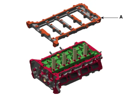
|
| 19. |
Remove the cam carrier (A).
|
| 20. |
Remove the hydraulic lash adjuster (HLA) (A) and swing arm (B).
|
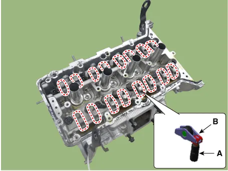
| 21. |
Remove the spark plug.
(Refer to Engine Electrical System - "Spark Plug")
|
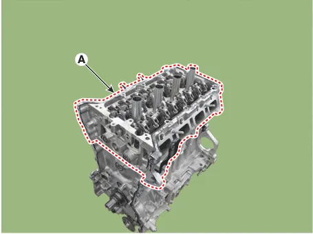
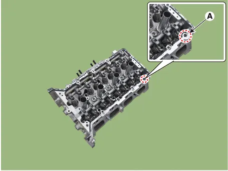
| 22. |
Remove the cylinder head.
|
| Disassembly |
| 1. |
Remove the valves.
|
| Inspection |
Cylinder Head
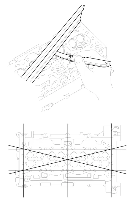
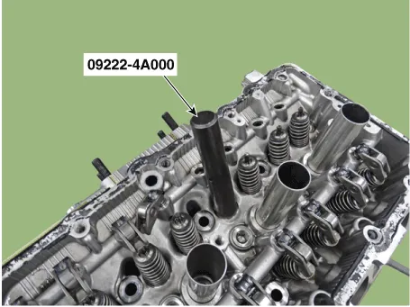
| 1. |
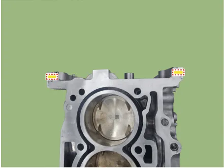
Inspect for flatness.
Using a precision straight edge and feeler gauge, measure the surface
the contacting the cylinder block and the manifolds for warpage.
|
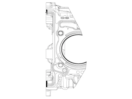
| 2. |
Inspect for cracks.
Check the combustion chamber, intake ports, exhaust ports and cylinder
block surface for cracks. If cracked, replace the cylinder head.
|
Valve And Valve Spring
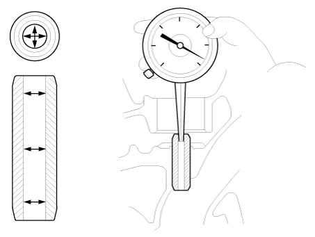
| 1. |
Inspect valve stems and valve guides.
|
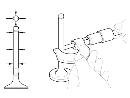
| 2. |
Inspect the valves.
|

| 3. |
Inspect the valve seats
|
| 4. |
Inspect the valve springs.
|
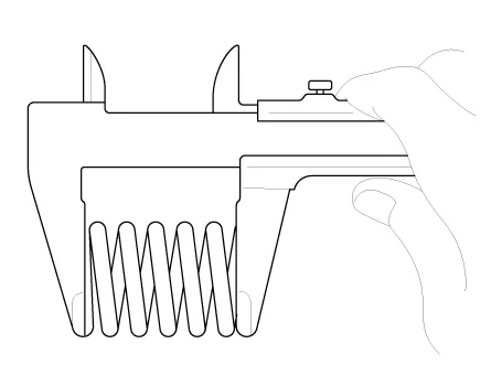
| Reassembly |
|
| 1. |
Install valves.
|
| 2. |
Install the MLAs after appling engine oil.
|
| Installation |
|
| 1. |
Install the cylinder head.
|
| 2. |
Install the cylinder head assembly.
|
| 3. |
Install the spark plugs.
(Refer to Engine Electrical System - "Spark Plug")
|
| 4. |
Install the hydraulic lash adjuster (HLA) (A) and the swing arm (B).
|
| 5. |
Install the cam carrier to the cylinder head.
|
| 6. |
Install the cam carrier (A).
|
| 7. |
Install the intake CVVT & camshaft assembly (A).
|
| 8. |
Install the exhaust CVVT & camshaft assembly (A).
|
| 9. |
Install the camshaft front bearing cap (A) and camshaft bearing caps
(B).
|
| 10. |
Install the other parts in the reverse order of removal.
|
| 11. |
Fill with engine coolant.
(Refer to Cooling System - "Coolant")
|
| 12. |
Refill engine with engine oil.
(Refer to Lubrication System - "Engine Oil")
|
Components and components location Components 1. Front oil seal 2. Timing chain cover 3. Timing chain 4. Cam to cam bracket 5.
Categories
- Manuals Home
- Hyundai Santa Fe Owners Manual
- Hyundai Santa Fe Service Manual
- Instrument cluster
- Hydraulic System
- 4 Wheel Drive (4WD) System
- New on site
- Most important about car

Copyright © 2026 www.hsafe4.com - 0.0205