Hyundai Santa Fe: Timing System / Timing Chain. Repair procedures
Hyundai Santa Fe (TM) 2019-2025 Service Manual / Engine Mechanical System / Timing System / Timing Chain. Repair procedures
| Removal |
|

| 1. |
Remove the cylinder head cover.
(Refer to Cylinder Head Assembly - "Cylinder Head Cover")
|
| 2. |
Set No.1 cylinder to top dead center (TDC) on compression stroke.
|
| 3. |
Remove the timing chain cover.
(Refer to Timing System - "Timing Chain Cover")
|
| 4. |
Remove the timing chain tensioner (A).
|

| 5. |
Remove the timing chain tensioner arm (A).
|
| 6. |
Remove the timing chain guide (A).
|
| 7. |
Remove the cam to cam guide (A).
|
| 8. |
Remove the timing chain (A).
|
| Inspection |
Sprockets, Hydraulic Tensioner, Chain Guide, Tensioner Arm, Timing Chain
| 1. |
Check the CVVT sprocket, crankshaft sprocket teeth for abnormal wear,
cracks or damage. Replace if necessary.
|
| 2. |
Check a contact surface of the chain tensioner arm and guide for abnormal
wear, cracks or damage.
Replace if necessary.
|
| 3. |
Check the hydraulic tensioner for its piston stroke and ratchet operation.
Replace if necessary.
|
| 4. |
Check the timing chain for its elongation, abnormal wear or damage.
Replace if necessary.
|
| Installation |
| 1. |
Install the timing chain (A).
|
| 2. |
Install the timing chain guide (A).
|
| 3. |
Install the timing chain tensioner arm (A).
|
| 4. |
Install the timing chain tensioner (A) and then remove the timing chain
tensioner fixing pin.
|
| 5. |
Install the cam to cam guide (A).
|
| 6. |
Check if the TDC mark at the front of intake and exhaust CVVT on right
side 0° by turning crankshaft twice to clockwise.
[CVVT timing mark]
[Crankshaft sprocket timing mark]
|
| 7. |
Install the timing chain cover.
(Refer to Timing System - "Timing Chain Cover")
|
| 8. |
Install the other parts in the reverse order of removal.
|
 Timing Chain Cover. Repair procedures
Removal
•
Be careful not to damage the parts located under the vehicle
(floor under cover, fuel filter, fuel tank and canister) when
raising the vehicle using the lift...

Other information:
Hyundai Santa Fe (TM) 2019-2025 Service Manual: Relay Box (Engine Compartment). Components and components location
..
Hyundai Santa Fe (TM) 2019-2025 Service Manual: Side Sill Molding. Repair procedures
Replacement • Put on gloves to prevent hand injuries. • When removing with a flat-tip screwdriver or remover, wrap protective tape around the tools to prevent damage to components...
Categories
- Manuals Home
- 4th Generation Santa Fe Owners Manual
- 4th Generation Santa Fe Service Manual
- Engine Control System
- Folding the side view mirror
- Warning and indicator lights
- New on site
- Most important about car
Air bag - supplemental restraint system
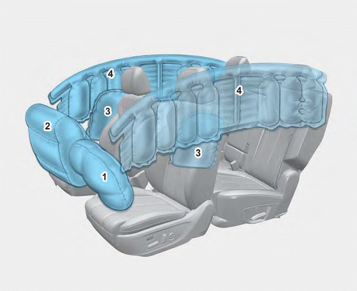
1. Driver’s front air bag
2. Passenger’s front air bag
3. Side air bag
4. Curtain air bag
The vehicles are equipped with a Supplemental Air Bag System for the driver’s seat and front passenger’s seats.
The front air bags are designed to supplement the three-point seat belts. For these air bags to provide protection, the seat belts must be worn at all times when driving.

Copyright © 2025 www.hsafe4.com