Hyundai Santa Fe: Cylinder Head Assembly / Cylinder Head. Repair procedures
| •
|
Be careful not to damage the parts located under the vehicle
(floor under cover, fuel filter, fuel tank and canister) when
raising the vehicle using the lift.
(Refer to General Information - "Lift and Support Points")
|
|
| •
|
Use fender covers to avoid damaging painted surfaces.
|
| •
|
To avoid damaging the cylinder head, wait until the engine coolant
temperature drops below normal temperature before removing it.
|
| •
|
When handling a metal gasket, take care not to fold the gasket
or damage the contact surface of the gasket.
|
| •
|
To avoid damage, unplug the wiring connectors carefully while
holding the connector portion.
|
|
| •
|
Mark all wiring and hoses to avoid misconnection.
|
|
|
1. |
Disconnect the battery negative terminal.
|
|
2. |
Remove the engine cover.
(Refer to Engine and Transaxle Assembly - "Engine Cover")
|
|
3. |
Remove the engine room under cover.
(Refer to Engine and Transaxle Assembly - "Engine Room Under Cover")
|
|
4. |
Drain the coolant.
(Refer to Cooling System - "Coolant")
|
|
5. |
Drain the engine oil.
(Refer to Lubrication System - "Engine Oil")
|
|
6. |
Remove the air duct and air cleaner assembly.
(Refer to Intake and Exhaust System - "Air Cleaner")
|
|
7. |
Remove the battery tray.
(Refer to Engine Electrical System - "Battery")
|
|
8. |
Disconnect the radiator upper hose (A).
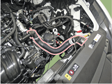
|
|
9. |
Disconnect the brake vacuum hose (A).
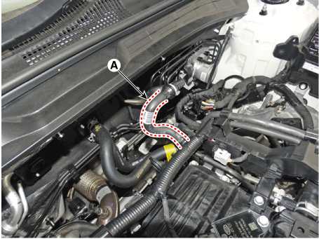
|
|
10. |
Disconnect the fuel hose (A) and purge control solenoid valve (PCSV)
hose (B).
|
|
11. |
Remove the delivery pipe.
(Refer to Engine Control / Fuel System - "Delivery Pipe")
|
|
12. |
Remove the intake manifold.
(Refer to Intake and Exhaust System - "Intake Manifold")
|
|
13. |
Remove the exhaust manifold.
(Refer to Intake and Exhaust System - "Exhaust Manifold")
|
|
14. |
Remove the water temperature control assembly.
(Refer to Cooling System - "Water Temperature Control Assembly")
|
|
15. |
Remove the timing chain.
(Refer to Timing System - "Timing Chain")
|
|
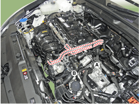
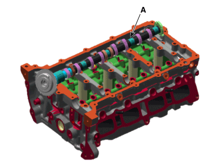
16. |
Remove the camshaft front bearing cap (A) and camshaft bearing caps
(B).
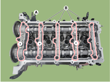
|
|
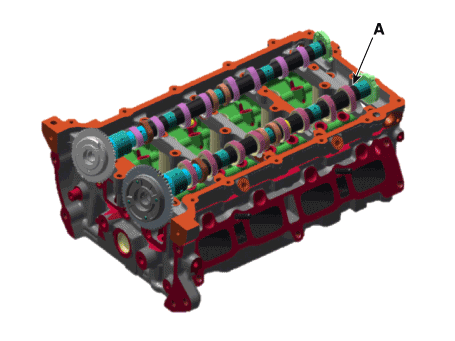
17. |
Remove the intake camshaft & CVVT assembly (A).
|
|
18. |
Remove the exhaust camshaft & CVVT assembly (A).
|
|
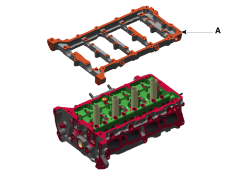
19. |
Remove the cam carrier (A).
|
|
20. |
Remove the hydraulic lash adjuster (HLA) (A) and swing arm (B).
|
|
21. |
Remove the spark plug.
(Refer to Engine Electrical System - "Spark Plug")
|
|
22. |
Remove the cylinder head.
|
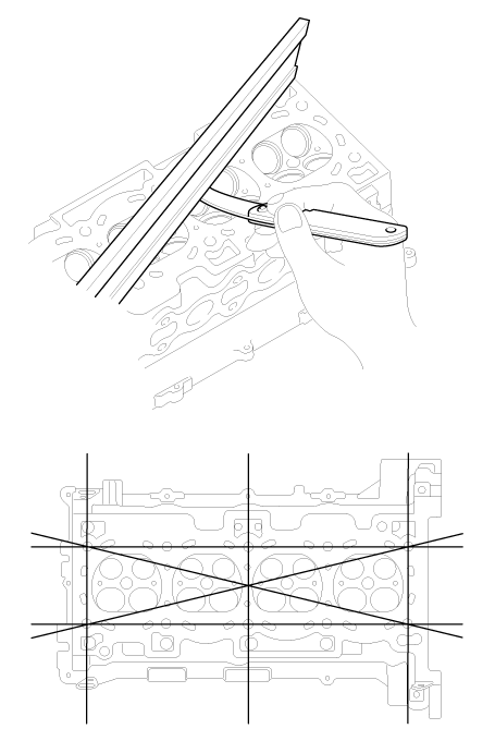
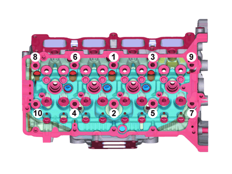
(1) |
Uniformly loosen and remove the cylinder head bolts, in several
passes, in the sequence shown.
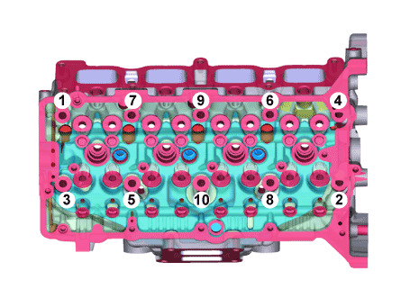
|
• |
Head warpage or cracking could result from removing
bolts in an incorrect order.
|
|
|
|
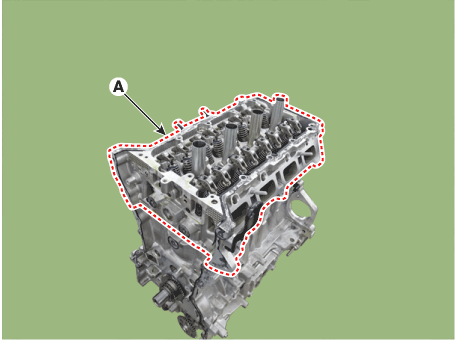
(2) |
Lift the cylinder head (A) from the dowels on the cylinder block
and place the cylinder head on wooden blocks on a bench.
|
• |
Be careful not to damage the contact surfaces
of the cylinder head and cylinder block.
|
|
|
|
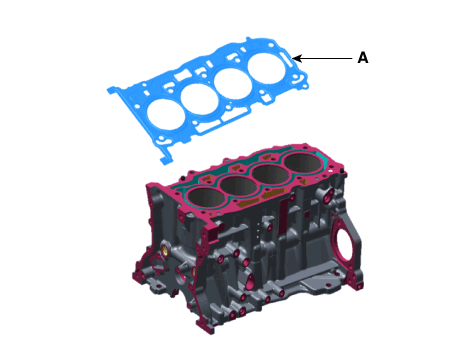
(3) |
Remove the cylinder head gasket (A).
|
• |
Do not reuse the cylinder head gasket.
|
|
|
|
|
1. |
Remove the valves.
|
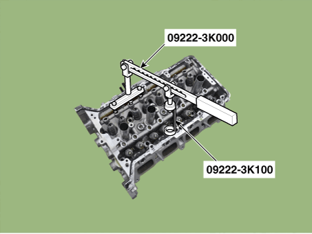
(1) |
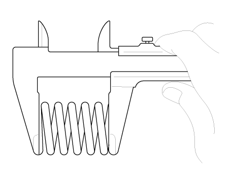
Using SST (09222-3K000, 09222-3K100), compress the valve spring
and remove retainer lock.
|
|
(2) |
Remove the spring retainer.
|
|
(3) |
Remove the valve spring.
|
|
(5) |
Using needle-nose pliers, remove the valve stem seal.
|
• |
Do not reuse old valve stem seals.
|
|
|
|
Cylinder Head
|
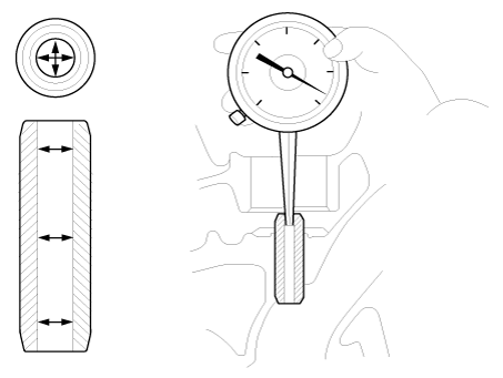
1. |
Inspect for flatness.
Using a precision straight edge and feeler gauge, measure the surface
the contacting the cylinder block and the manifolds for warpage.
|
Flatness of cylinder head gasket surface
Standard : Less than 0.05 mm (0.0019 in.) for total area
Less than 0.02 mm (0.0007 in.) for a section of 100 mm (3.9370
in.) X 100 mm (3.9370 in.)
Flatness of manifold mounting surface (Intake/Exhaust)
Standard : Less than 0.10 mm (0.0039 in.)
|
|
|
2. |
Inspect for cracks.
Check the combustion chamber, intake ports, exhaust ports and cylinder
block surface for cracks. If cracked, replace the cylinder head.
|
Valve And Valve Spring
|
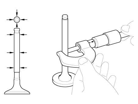
1. |
Inspect valve stems and valve guides.
|
(1) |
Using a caliper gauge, measure the inside diameter of the valve
guide.
|
Valve guide inner diameter
Intake / Exhaust :
5.500 - 5.512 mm (0.21654 - 0.21701 in.)
|
|
|
(2) |
Using a micrometer, measure the diameter of the valve stem.
|
Valve stem outer diameter
Intake : 5.460 - 5.475 mm (0.2150 - 0.2156 in.)
Exhaust : 5.453 - 5.465 mm (0.2147 - 0.2152 in.)
|
|
|
(3) |
Subtract the valve stem diameter measurement from the valve
guide inside diameter measurement.
|
Valve stem-to-guide clearance
[Standard]
Intake : 0.020 - 0.047 mm (0.00078 - 0.00185 in.)
Exhaust : 0.030 - 0.054 mm (0.00118 - 0.00212 in.)
[Limit]
Intake : 0.070 mm (0.00275 in.)
Exhaust : 0.090 mm (0.00354 in.)
|
If the clearance is greater than maximum, replace the valve
or cylinder head.
|
|
|
2. |
Inspect the valves.
|
(1) |
Check the valve is ground to the correct valve face angle.
|
|
(2) |
Check that the surface of the valve for wear.
If the valve face is worn, replace the valve.
|
|
(3) |
Check the valve head margin thickness.
|
Valve head thickness (Margin)
[Standard]
Intake : 0.8 mm (0.03150 in.)
Exhaust : 0.8 mm (0.03150 in.)
|
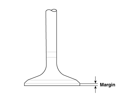
If the margin thickness is less than minimum, replace the valve.
|
|
(4) |
Check the valve length.
|
Valve length
[Standard]
Intake : 108.378 mm (4.2669 in.)
Exhaust :119.878 mm (4.7196 in.)
[Limit]
Intake : 108.228 mm (4.2609 in.)
Exhaust : 119.728 mm (4.7137 in.)
|
|
|
(5) |
Check the surface of the valve stem tip for wear.
If the valve stem tip is worn, replace the valve.
|
|
|
3. |
Inspect the valve seats
|
(1) |
Check the valve seat for evidence of overheating and improper
contact with the valve face. Replace the cylinder head if necessary.
|
|
(2) |
Check the valve guide for wear. If the valve guide is worn,
replace the cylinder head.
|
|
|
4. |
Inspect the valve springs.
|
(1) |
Using a steel square, measure the out-of-square of the valve
spring.
|
|
(2) |
Using a vernier calipers, measure the free length of the valve
spring.
|
Valve spring
[Standard]
Free height : 52.51 mm (2.0673 in.)
Out-of-square : Less than 1.5°
|
If the free length is not as specified, replace the valve spring.
|
|
| •
|
Thoroughly clean all parts to be assembled.
Before installing the parts, apply fresh engine oil to all sliding
and rotating surfaces.
Replace oil seals with new ones.
|
|
|
1. |
Install valves.
|
(1) |
After applying engine oil to the valve stem seal, install a
new valve stem seal using the special tool (09222-2B100).
|
• |
Always use new valve stem seals.
|
|
• |
Incorrect installation of the seal could result
in oil leakage past the valve guides.
|
|
|
|
(2) |
Install the valve, valve spring and spring retainer.
|
• |
Place valve springs so that the side coated
with enamel faces toward the valve spring retainer
and then installs the retainer.
|
|
|
|
(3) |
Using the SST (09222-3K000, 09222-3K100), compress the spring
and install the retainer locks. After installing the valves,
ensure that the retainer locks are correctly in place before
releasing the valve spring compressor.
|
|
(4) |
Lightly tap the end of each valve stem two or three times with
the wooden handle of a hammer to ensure proper seating of the
valve and retainer lock.
|
|
|
2. |
Install the MLAs after appling engine oil.
|
| •
|
Thoroughly clean all parts to be assembled.
|
| •
|
Always use a new cylinder head gasket and manifold gasket.
|
| •
|
Always use a new cylinder head bolt and cylinder head bolt washer.
|
| •
|
The cylinder head and exhaust manifold is a metal gasket. Take
care not to bend it.
|
| •
|
Turn the crankshaft pulley so that the No. 1 piston is at top
dead center.
|
|
|
1. |
Install the cylinder head.
|
(1) |
Remove hardening sealant, oil, dust, moisture and harmful foreign
materials from the cylinder block and the cylinder head.
|
|
(2) |
Apply liquid sealant on the upper surface of the cylinder block.
|
Width : 2.0 - 3.0 mm (0.0787 - 0.1181 in.)
Specification : MS721-40 TYPE "AA" or "AAO"
|
|
|
(3) |
Install the cylinder head gasket (A) to the cylinder block.
|
• |
Be careful of the installation direction.
|
|
|
|
(4) |
Apply liquid sealant on the upper surface of the cylinder head
gasket.
|
Width : 2.0 - 3.0 mm (0.0787 - 0.1181 in.)
Specification : MS721-40 TYPE "AA" or "AAO"
|
|
|
|
2. |
Install the cylinder head assembly.
|
(1) |
Place the cylinder head assembly (A) quietly in order not to
damage the gasket with the bottom part of the end.
|
|
(2) |
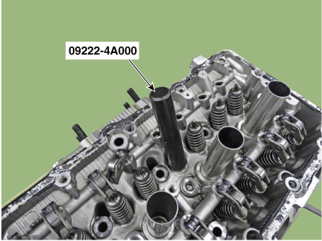
Using SST (09221-4A000), tighten the cylinder head bolts and
plate washers, in several passes, in the sequence shown.
|
Tightening torque :
32.4 - 36.3 N.m (3.3 - 3.7 kgf.m, 23.9 - 26.8 lb-ft)
+ [90° - 94°] + [110° - 114°]
|
|
• |
Do not reuse the cylinder head bolts.
|
|
• |
Do not apply engine oil on the bolt threads
to achieve correct torque.
|
|
• |
Remove the extruded sealant within 5 minutes
after installing cylinder head bolts.
|
|
• |
The engine running or pressure test should not
be performed within 30minutes after installing
cylinder head bolts.
|
|
• |
Be careful not to change the installing position
of the preassembled washer bolts and non-preassembled
washer bolts.
|
|
|
|
|
3. |
Install the spark plugs.
(Refer to Engine Electrical System - "Spark Plug")
|
|
4. |
Install the hydraulic lash adjuster (HLA) (A) and the swing arm (B).
|
|
5. |
Install the cam carrier to the cylinder head.
|
(1) |
Remove hardening sealant, oil, dust, moisture and harmful foreign
materials from the bottom surface of the cam carrier and top
surface of the cylinder head.
|
|
(2) |
After applying liquid sealant on the bottom surface of the cam
carrier, Continuous bead of sealant should be applied to prevent
any path from oil leakage.
|
Width : 2.0 - 3.0 mm (0.0787 - 0.1181 in.)
Specification : MS721-40 TYPE "AA" or "AAO"
|
|
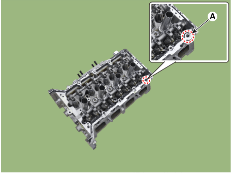
• |
When installing the cam carrier to the cylinder
head, make sure to prevent the sealant from
entering the hole (A) and the positive crankcase
ventilation (PCV).
|
|
|
|
|
6. |
Install the cam carrier (A).
|
Tightening torque :
18.6 - 22.6 N.m (1.9 - 2.3 kgf.m, 13.7 - 16.6 lb-ft)
|
|
• |
Assemble the cam carrier within 5 minutes after applying
sealant.
|
|
• |
Assemble the camshaft bearing cap within 5 minutes after
assembling the cam carrier.
|
|
• |
The engine running or pressure test should not be performed
within 30 minutes after assembling the cam carrier.
|
|
• |
After installing the cam carrier to the cylinder head,
check whether there are sealants in the hole of the
oil level gauge and the positive crankcase ventilation
(PCV).
|
|
|
|
7. |
Install the intake CVVT & camshaft assembly (A).
|
|
8. |
Install the exhaust CVVT & camshaft assembly (A).
|
|
9. |
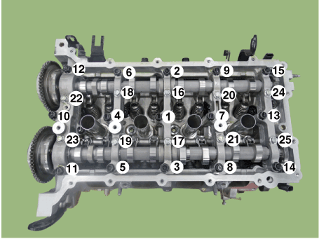
Install the camshaft front bearing cap (A) and camshaft bearing caps
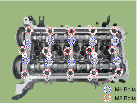
(B).
|
• |
When installing the camshaft front bearing cap and camshaft
bearing caps, tighten the bolts and nuts with pre-torque
first, and then tighten the bolts and nuts with specified
torque in the sequence shown.
|
Tightening torque :
Step 1
M8 Bolts : 9.8 - 11.8 N.m (1.0 - 1.2 kgf.m,
7.2 - 8.7 lb-ft)
M6 Bolts : 4.9 - 7.8 N.m (0.5 - 0.8 kgf.m, 3.6
- 5.8 Ib-ft)
Step 2
M8 Bolts : 18.6 - 22.6 N.m (1.9 - 2.3 kgf.m,
13.7 - 16.6 lb-ft)
M6 Bolts : 11.8 - 13.7 N.m (1.2 - 1.4 kgf.m,
8.7 - 10.1 lb-ft)
|
|
|
|
|
10. |
Install the other parts in the reverse order of removal.
|
|
11. |
Fill with engine coolant.
(Refer to Cooling System - "Coolant")
|
|
12. |
Refill engine with engine oil.
(Refer to Lubrication System - "Engine Oil")
|
Removal
•
Be careful not to damage the parts located under the vehicle
(floor under cover, fuel filter, fuel tank and canister) when
raising the vehicle using the lift...
Other information:
..
Component Location
[Second row seat assembly]
1. Rear seat
cushion cover [LH]
2. Rear seat
cushion cover [RH]
[Third row seat assembly]
1. Rear seat
cushion cover [LH]
2...
Categories
1. Inside door handle
2. Power window switches
3. Power window lock button/Electronic child safety lock button
4. Side view mirror folding button
5. Side view mirror control switch
6. Central door lock switch
7. Instrument panel illumination control switch
read more


 CVVT & Camshaft. Repair procedures
