Hyundai Santa Fe (TM): Cylinder Head Assembly / CVVT & Camshaft. Repair procedures
| Removal |
|

| 1. |
Remove the timing chain.
(Refer to Timing System - "Timing Chain")
|
| 2. |
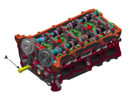
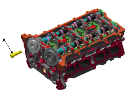
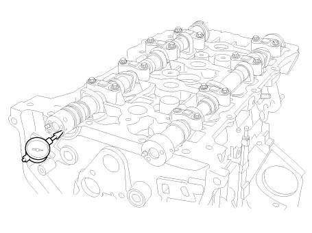
Remove the oil control valve (OCV) and center bolt (A).
[Intake oil control valve (OCV) and Center Bolt]
[Exhaust oil control valve (OCV) and Center Bolt]
|

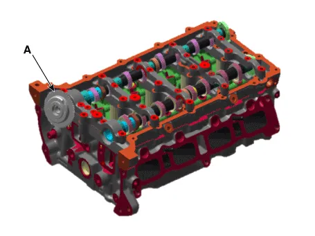
| 3. |
Remove the intake CVVT (A).
|
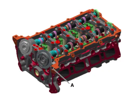
| 4. |
Remove the exhaust CVVT (A).
|
| 5. |
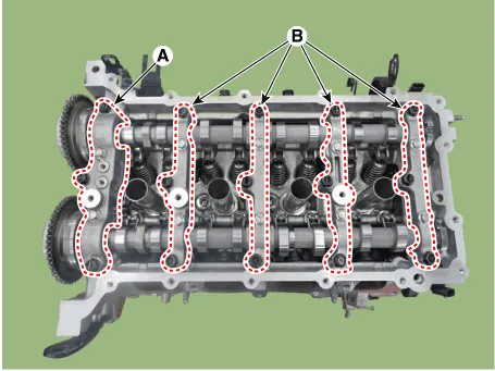
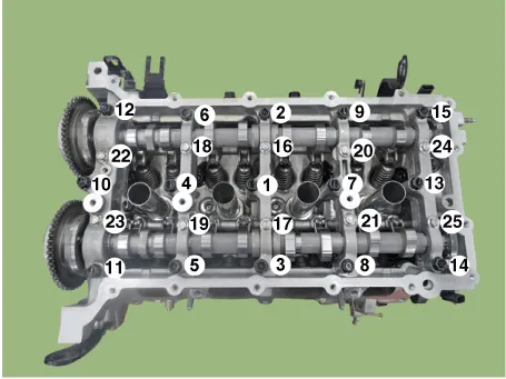
Remove the camshaft front bearing cap (A) and camshaft bearing caps
(B).
|
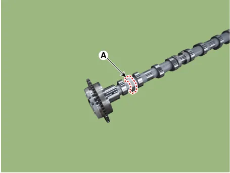
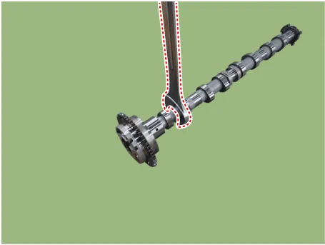
| 6. |
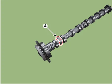
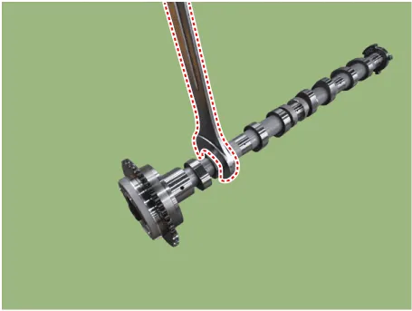
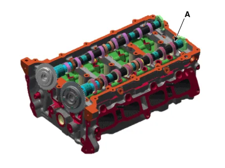
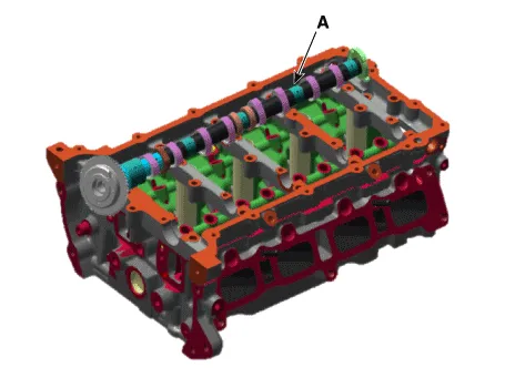
Remove the camshaft (A).
[Intake Camshaft]
[Exhaust Camshaft]
|
| 1. |
Remove the timing chain.
(Refer to Timing System - "Timing Chain")
|
| 2. |
Remove the camshaft front bearing cap (A) and camshaft bearing caps
(B).
|
| 3. |
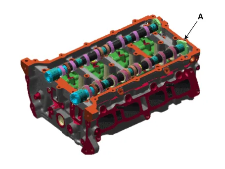
Remove the intake camshaft & CVVT assembly (A).
|
| 4. |
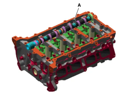
Remove the exhaust camshaft & CVVT assembly (A).
|
| Inspection |
| 1. |
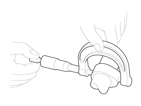
Inspect the cam lobes.
Using a micrometer, measure the cam lobe height.
If the cam lobe height is less than standard, replace the camshaft.
|
| 2. |
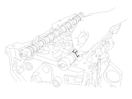
Inspect the camshaft journal clearance.
|
| 3. |
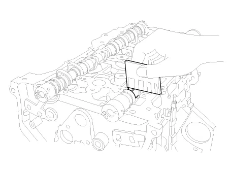
Inspect the camshaft end play.
|
| Installation |
| 1. |
Install the camshaft (A).
[Intake Camshaft]
[Exhaust Camshaft]
|
| 2. |
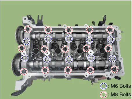
Install the camshaft front bearing cap (A) and camshaft bearing caps
(B).
|

| 3. |
Install the exhaust CVVT (A).
|
| 4. |
Install the intake CVVT (A).
|
| 5. |
Install the oil control valve (OCV) and center bolt (A).
[Intake oil control valve (OCV) and Center Bolt]
[Exhaust oil control valve (OCV) and Center Bolt]
|
| 6. |
Install the timing chain.
(Refer to Timing System - "Timing Chain")
|
| 1. |
Install the exhaust camshaft & CVVT assembly (A).
|
| 2. |
Install the intake camshaft & CVVT assembly (A).
|
| 3. |
Install the camshaft front bearing cap (A) and camshaft bearing caps
(B).
|
| 4. |
Install the timing chain.
(Refer to Timing System - "Timing Chain")
|
Description Continuous Variable Valve Timing (CVVT) system advances or retards the valve timing of the intake and exhaust valve in accordance with the ECM control signal which is calculated by the engine speed and load.
Removal • Be careful not to damage the parts located under the vehicle (floor under cover, fuel filter, fuel tank and canister) when raising the vehicle using the lift.
Other information:
Hyundai Santa Fe (TM) 2019-2023 Service and Repair Manual: Components and components location
Hyundai Santa Fe (TM) 2019-2023 Service and Repair Manual: Repair procedures
Removal 1. Remove the tailgate trim. (Refer to Body - "Tailgate Trim") 2. Remove the tailgate ganish (A). 3. Remove the tailgate switch assembly.
Categories
- Manuals Home
- Hyundai Santa Fe Owners Manual
- Hyundai Santa Fe Service Manual
- Engine Electrical System
- Engine Mechanical System
- Driver assistance system
- New on site
- Most important about car
