Hyundai Santa Fe (TM): Cylinder Block / Cylinder Block. Repair procedures
| Disassembly |
|

|

|

| 1. |
Remove the crankshaft.
(Refer to Cylinder Block - "Crankshaft")
|
| 2. |
Remove the knock sensor.
(Refer to Engine Control / Fuel System - "Knock Sensor (KS)")
|
| 3. |
Remove the crankshaft position sensor (CKPS).
(Refer to Engine Control / Fuel System - "Crankshaft Position Sensor
(CKPS)")
|
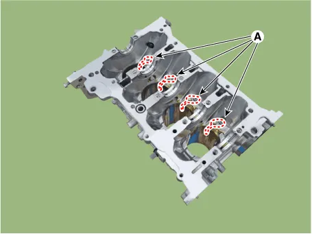
| 4. |
Remove the piston cooling oil jets (A).
|
| Inspection |
| 1. |
Using a gasket scraper, remove all the gasket material from the top
surface of the cylinder block.
|
| 2. |
Using a soft brush and solvent, thoroughly clean the cylinder block.
|
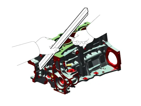
| 3. |
Inspect the top surface of cylinder block for flatness.
Using a precision straight edge and feeler gauge, measure the surface
contacting the cylinder head gasket for warpage.
|
| 4. |
Visually check for scratches on the inside surface of the cylinder bore
and replace the cylinder block if any noticeable scratch is detected.
If deep scratchs are present, replace the cylinder block.
|
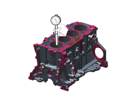
| 5. |
Using the cylinder bore gauge, measure the cylinder bore’s inner diameter
to the axial and axial perpendicular directions.
|
| Reassembly |
|
| 1. |
Install the piston cooling oil jets (A).
|
| 2. |
Install the crankshaft.
(Refer to Cylinder Block - "Crankshaft")
|
| 3. |
Check the crankshaft end play.
(Refer to Cylinder Block - "Crankshaft")
|
| 4. |
Disconnect the lower crankcase and check crankshaft bearing oil clearance.
(Refer to Cylinder Block - "Crankshaft")
|
| 5. |
Install the piston and connecting rod assembly.
(Refer to Cylinder Block - "Piston and Connecting Rod")
|
| 6. |
Check the connecting rod bearing cap oil clearance.
(Refer to Cylinder Block - "Piston and Connecting Rod")
|
| 7. |
Check the connecting rod end play.
(Refer to Cylinder Block - "Piston and Connecting Rod")
|
| 8. |
Assemble the other parts in the reverse order of disassembly.
|
Disassembly • Be careful not to damage the parts located under the vehicle (floor under cover, fuel filter, fuel tank and canister) when raising the vehicle using the lift.
Coolant. Repair procedures Refilling And Bleeding • Never remove the reservoir tank cap when the engine is hot.
Other information:
Hyundai Santa Fe (TM) 2019-2023 Service and Repair Manual: Power Tailgate Module
Description and operation Description Power tailgate is an electro-mechanical system designed to provide power opening and closing of the tailgate through the push of a button of a remote key (fob), console switch, inner switch or an outside handle switch of the tailgate.
Hyundai Santa Fe (TM) 2019-2023 Service and Repair Manual: Rear Wiper/Washer
Components and components location Component Location 1. Rear wiper arm nut 2. Rear wiper arm & blade 3. Rear wiper grommet 4. Rear wiper motor assembly Rear Wiper Motor. Repair procedures Inspection Rear Wiper Motor 1.
Categories
- Manuals Home
- Hyundai Santa Fe Owners Manual
- Hyundai Santa Fe Service Manual
- Engine Mechanical System
- Emission Control System
- Vehicle Information, Consumer Information and Reporting Safety Defects
- New on site
- Most important about car
