Hyundai Santa Fe (TM): Brake System / Brake Pedal. Repair procedures
| Removal |
| 1. |
Turn ignition switch OFF and disconnect the negative (-) battery cable.
|
| 2. |
Remove the crash pad lower panel.
(Refer to Body - "Crash Pad Lower Panel")
|
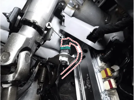
| 3. |
Disconnect the stop lamp switch connector (A).
|
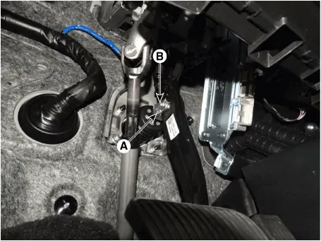
| 4. |
Separate the snap pin (A) and clevis pin (B).
|
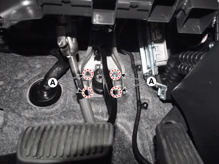
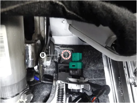
| 5. |
Remove the brake pedal assembly after loosening the mounting bolts (B)
and nuts (A).
|
| Inspection |
| 1. |
Check the brake pedal for bending or twisting.
|
| 2. |
Check the brake pedal return spring for damage.
|
| 3. |
Check the stop lamp switch.
(Refer to Brake System - "Stop Lamp Switch")
|
| Installation |
| 1. |
To install, reverse the removal procedures.
|

Components 1. Brake member assembly 2. Stop lamp switch 3. Brake pedal arm assembly 4. Brake pedal pad
Components 1. Caliper body 2. Caliper carrier 3. Pad inner shim 4. Brake pad 5. Pad retainer
Other information:
Hyundai Santa Fe (TM) 2019-2023 Service and Repair Manual: Auto Lighting Control System
Description and operation Description It's a system that uses illumination sensor to automatically turn ON the tail lamp and head lamp based on the change in surrounding environment's illumination condition. It activates when the vehicle enters/exits tunnel, or when the illumination condition in surrounding environ
Hyundai Santa Fe (TM) 2019-2023 Service and Repair Manual: Front View Camera System
Description and operation Description and Operation Blcok Diagram • This system monitors the driving situations through the radar and the camera.
Categories
- Manuals Home
- Hyundai Santa Fe Owners Manual
- Hyundai Santa Fe Service Manual
- Front Radar Unit. Repair procedures
- 4 Wheel Drive (4WD) System
- Troubleshooting
- New on site
- Most important about car
