Hyundai Santa Fe (TM): Engine Control System / Accelerator Position Sensor (APS). Specifications
| Specification |
|
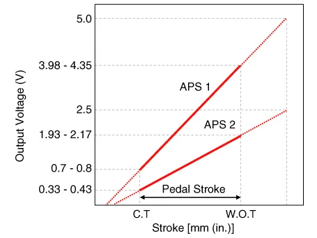
Accelerator Position |
Output Voltage (V) [Vref=5V] |
|
|
APS 1 |
APS 2 |
|
|
C.T |
0.7 - 0.8 |
0.33 - 0.43 |
|
W.O.T |
3.98 - 4.35 |
1.93 - 2.17 |
Description On electronic injection systems, there is no longer a load lever that mechanically controls the fuelling. The flow is caculated by the ECM depending on a number of parameters, including pedal position, which is measured using a potentiometer.
Circuit Diagram Harness Connector
Other information:
Hyundai Santa Fe (TM) 2019-2023 Service and Repair Manual: Smart Key. Repair procedures
Smart Key Smart Key Code Saving 1. Connect the DLC cable of diagnostic tool to the data link connector (16 pins) in driver side crash pad lower panel, turn the power on diagnostic tool. 2.
Hyundai Santa Fe (TM) 2019-2023 Service and Repair Manual: Fuel Filler Door
Components and components location Component Location 1. Fuel filler door release actuator Fuel Filler Door Release Actuator. Repair procedures Removal 1. Remove the left luggage side trim.
Categories
- Manuals Home
- Hyundai Santa Fe Owners Manual
- Hyundai Santa Fe Service Manual
- Engine Electrical System
- Parking Brake System. Electronic Parking Brake (EPB)
- Electronic Parking Brake (EPB)
- New on site
- Most important about car
