Hyundai Santa Fe (TM): Body Electrical System / AC Inverter System
Description and operation
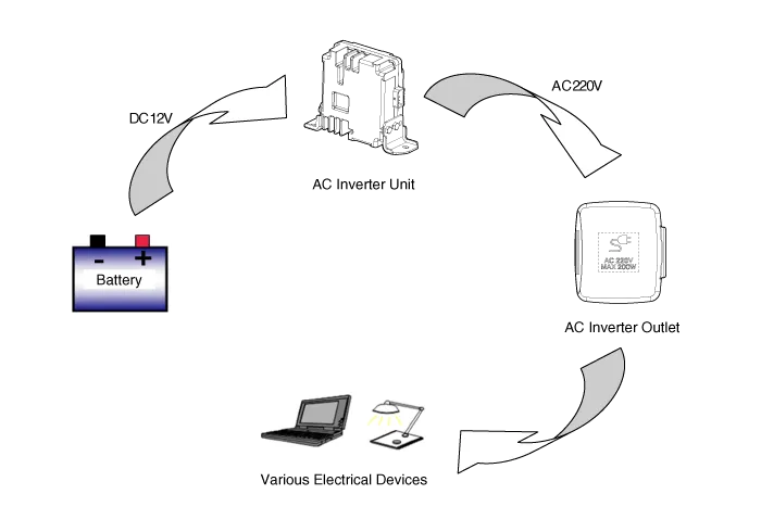
An inverter is a device that transforms the DC voltage from the battery into
an AC voltage (220 V). The inverter can power various electrical devices that
consume 200 W or less, including mobile phone or notebook rechargers, audio
systems, and TVs.
Inverter System Protection Function
Item
|
Condition
|
LED Status
|
Undervoltage protection
|
Shuts down for safety at voltages lower than 11.3 V ± 0.3 V.
|
LED flickering
|
Resumes operation at 12.2 V ± 0.3 V.
|
LED lighting
|
Overvoltage protection
|
Shuts down for safety at voltages higher than 15.5 V ± 0.3 V.
|
LED flickering
|
Resumes operation at 15.5 V ± 0.3 V.
|
LED lighting
|
Overheat protection
|
Shuts down for safety if temperatures exceed 105°C ± 10°C.
|
LED flickering
|
Resumes operation at 95°C ± 10°C.
|
LED lighting
|
Overcurrent protection
|
Turns OFF when overcurrent above a set point is detected.
|
LED lighting
|
The inverter stops for 20 seconds before its restarts.
|
LED flickering
(20 seconds)
|
Turns OFF when overcurrent is detected 3 times (turn the AC inverter switch
ON again to turn on the inverter).
|
 
|
short circuit protection
|
The inverter shuts down for safety if there is a short circuit between the
AC1 and AC 2 outputs during operation.
|
LED OFF
|
undervoltage/overvoltage shutdown protection
|
Shuts down at voltages lower than 10.7 V ± 0.3 V.
|
LED OFF
|
Shuts down at voltages lower than 16.5 V ± 0.3 V.
|
LED OFF
|
| –
|
DO NOT touch or insert any foreign substance into the AC inverter.
Be aware of the potential risk of electric shock or fire.
|
|
| –
|
Only use the AC inverter when the engine is running. Always
disconnect the inverter when not in use.
|
| –
|
Using the AC inverter when the engine is off or leaving an electric
device plugged in for a long time may drain the battery of the
vehicle.
|
| –
|
DO NOT use any electric devices that consume more than 220 V
(200 W) of power.
|
| –
|
Connecting an electrical device that generates excessive levels
of electromagnetic noise to the AC inverter may cause abnormal
sounds in the audio equipment or a malfunction in the vehicle's
electronic devices.
|
| –
|
Connecting a faulty electronic device to the AC inverter may
damage the inverter or the electric system of the vehicle.
|
|
| –
|
The LED indicator blinks if the AC inverter input voltage falls
below 11.3 V. The inverter shuts off if the voltage falls below
10.7 V.
Inspect the battery and recharging system.
|
|
Components and components location
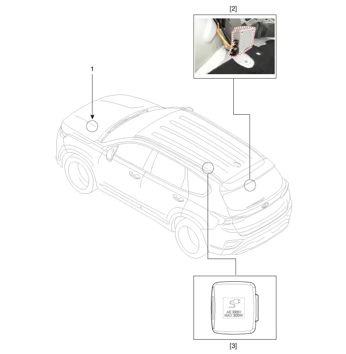
1. Battery
2. AC inverter Unit
|
3. AC inverter
outlet
|
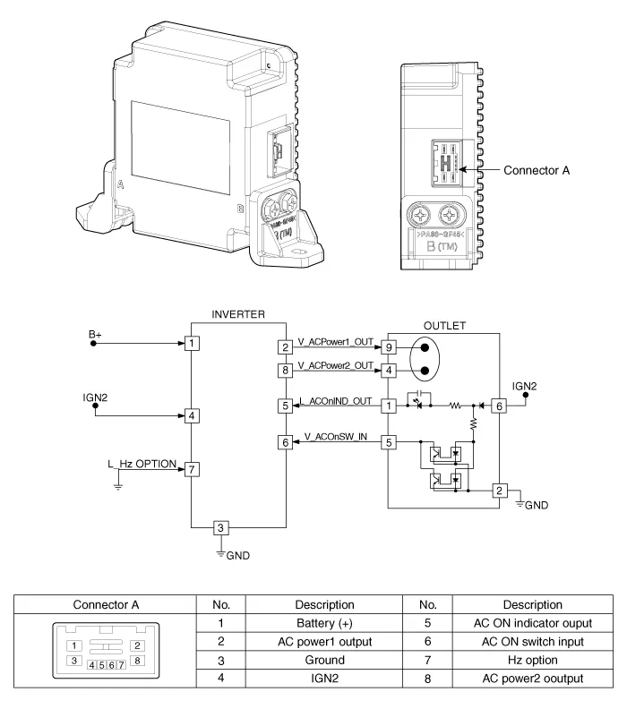
Specifications
Item
|
Specification
|
Rated Voltage
|
DC 12.5V
|
Operating voltage
|
DC 12.2 - 15.0V
|
Operating temperature
|
-30°C to 75°C
|
Output voltage
|
AC 198 - 242V (rms)
|
Output frequency
|
60 ± 6 Hz
|
Rated power
|
200W (-30°C - 45°C)
|
Current spec.
|
Full load input current : Max. 20A
Key OFF current : Max 1㎂
|
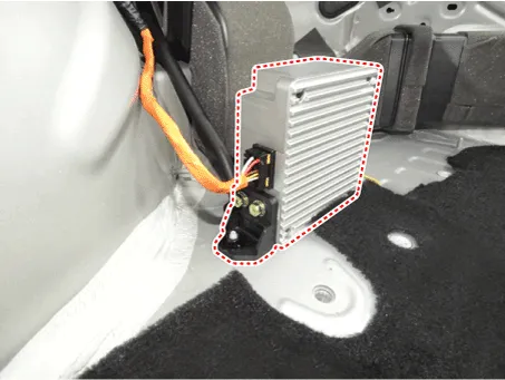
AC Inverter Unit. Components and components location
AC Inverter Unit. Repair procedures
|
1. |
Disconnect the negative (-) battery terminal.
|
|
2. |
Remove the right luggage side trim.
(Refer to Body - "Luggage Side Trim")
|
|
3. |
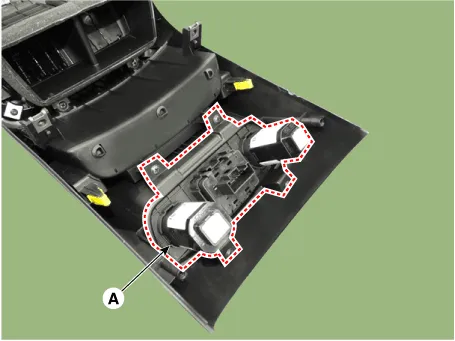
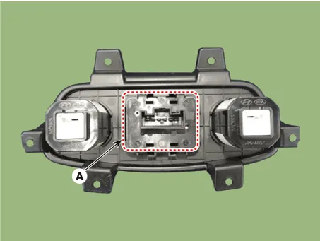
Disconnect the connector from the AC inverter unit.
|
|
4. |
Remove the AC inverter unit after loosening the mounting nuts (3EA).
|
|
1. |
Install the AC inverter unit.
|
|
2. |
Install the luggage side trim.
|
|
3. |
Connect the negative (-) battery terminal.
|
– |
Before starting repair work, turn off the engine and
AC inverter.
|
|
– |
You may get electrocuted if you work with the AC inverter
on.
|
|
– |
You may get electrocuted if you work on the AC inverter
with you hands wet.
|
|
|
AC Inverter Oultet. Repair procedures
|
1. |
Disconnect the negative (-) battery terminal.
|
|
2. |
Remove the rear console cover.
(Refer to Body - "Rear Console Cover")
|
|
3. |
Remove the power outlet cover (A).
|
|
4. |
Remove the power outlet switch (A) on the bracket.
|
|
1. |
Install the power outlet switch.
|
|
2. |
Install the power outlet cover.
|
|
3. |
Connect the negative (-) battery terminal.
|
Description and operation
Description
System Overview
The System offers the following features:
–
Changing the state of engine ignition and power by using the start button.
Description and operating principle
Description and Operation
Wireless Power Charger System
During ACC or IG ON, battery voltage is supplied to the wireless power charger
system to transmit an output of 5 W to mobile phone.
Other information:
Components and components location
Component Location
1. Fuel filler
door release actuator
Fuel Filler Door Release Actuator. Repair procedures
Removal
1.
Remove the left luggage side trim.
Description and operating principle
Description and Operation
Wireless Power Charger System
During ACC or IG ON, battery voltage is supplied to the wireless power charger
system to transmit an output of 5 W to mobile phone.
Mobile phones certified with the wireless charging standard WPC (Qi 1.


