Hyundai Santa Fe (TM): ESP(Electronic Stability Program) System / Yaw-rate and G Sensor. Repair procedures
Hyundai Santa Fe (TM) 2019-2023 Service and Repair Manual / Brake System / ESP(Electronic Stability Program) System / Yaw-rate and G Sensor. Repair procedures
| Removal |
| 1. |
Turn ignition switch OFF and disconnect the negative (-) battery cable.
|

| 2. |
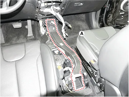
Remove the floor console.
(Refer to Body - "Floor Console")
|
| 3. |
Remove the air duct (A) after loosening the mounting bolts (A).
|
| 4. |
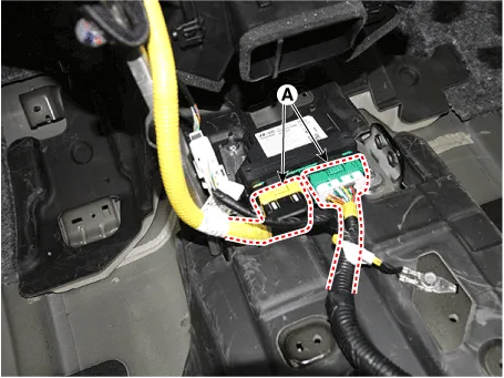
Pull up the lock, of the SRSCM connector, the disconnect the connector
(A).
|
| 5. |
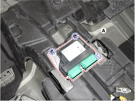
Remove the SRSCM (A) after loosening the mounting bolts and nuts.
|
| Installation |
| 1. |
To install, reverse the removal procedures.
|
| 2. |
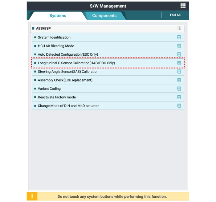
Perform Longitudinal G-sensor calibration in vehicle S/W Management
menu of the diagnostic tool.
|
| Adjustment |
As manual for diagnosis methods by using diagnosis device, the main contents
are as follows:
| 1. |
Connect self-diagnosis connector(16pins) located in the lower of driver
side crash pad to self-diagnosis device, and then turn the self-diagnosis
device after key is ON.
|
| 2. |
Select the "vehicle model" and "ABS/ESP" on diagnostic tool vehicle
selection screen, then select OK.
[Longitudinal G Sensor Calibration]
|
Schematic Diagrams
Other information:
Hyundai Santa Fe (TM) 2019-2023 Service and Repair Manual: AVN System
Description and operation Description AVN system The AVN system has improved information search and easiness of manipulation for the driver by simplifying the system operation experience and unifying the display of the user information such as multimedia and car information.
Hyundai Santa Fe (TM) 2019-2023 Service and Repair Manual: Parking Distance Warning (PDW)
Description and operation Description • PDW consists of 8 sensors (front : 4 units, rear : 4 units) that are used to detect obstacles and transmit the result in three separate warning levels, the first, second and third to IBU via LIN communication.
Categories
- Manuals Home
- Hyundai Santa Fe Owners Manual
- Hyundai Santa Fe Service Manual
- Engine Electrical System
- Restraint
- Electronic Parking Brake (EPB)
- New on site
- Most important about car

Copyright © 2026 www.hsafe4.com - 0.0246