Hyundai Santa Fe (TM): Suspension System / Tire Pressure Monitoring System
Components and components location
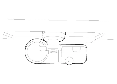
| Components Location |
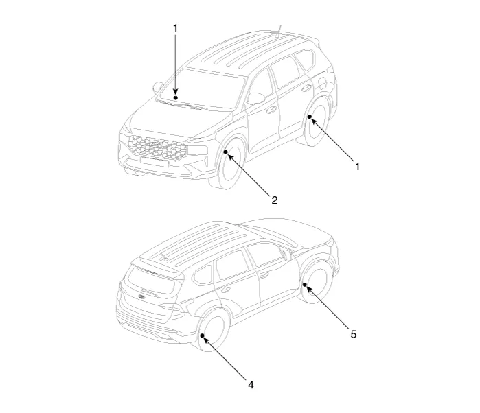
| 1. Receiver 2. TPMS Sensor (FL) 3. TPMS Sensor (RL) |
4. TPMS Sensor
(RR) 5. TPMS Sensor (FR) |
Description and operation
| Description |
| – |
Tire Under Inflation / Leak Warning.
|

| 1. |
Turn on condition
|
| 2. |
Turn off condition
|
| 1. |
Turn on condition
|
| 2. |
Turn off condition
|

| 1. |
General Function
|
TPMS Sensor. Description and operation
| Description |
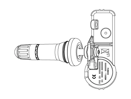
| 1. |
Driving state
Sensor transmissions occur every 1 minutes and pressure is measured
every 15 seconds.
|
| 2. |
Stationary state
Sensor transmissions does not occur and pressure is measured every 60
seconds.
|
| 3. |
Auto learning status
When driving after stopping more than 15 minutes , sensor transmissions
occur every 33 seconds and pressure is measured every 10.8 seconds.
|
| 4. |
Off status
The TPMS sensor is not operated.
Due to stock status, does not measured pressure, temperature, battery
status.
|
| 5. |
Alert State :
When a 2 psi change in pressure from the last transmission occurs, transmit
tire information immediately.
The pressure is measured every 2 seconds.
|
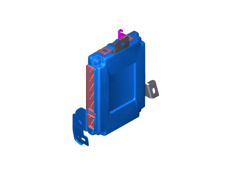
TPMS Sensor. Repair procedures
| Replacement |
| 1. |
Remove the tire.
(Refer to Tires/Wheels - "Tire")
|
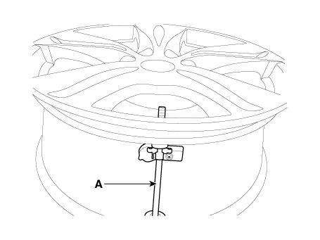
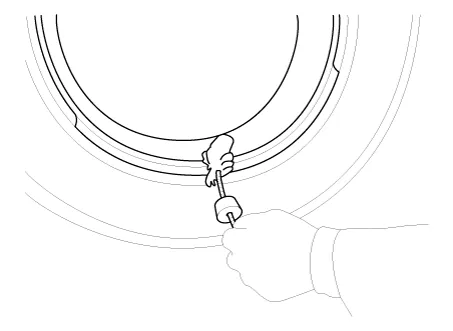
| 2. |
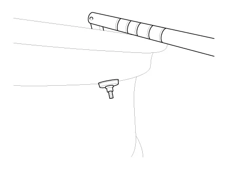
Remove the screw with torx driver (A).
|

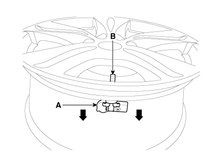
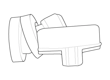
| 3. |
Remove the sensor body (A) from the valve (B) in the direction of the
arrow.
|
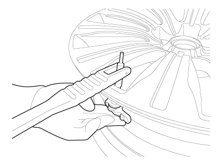
| 4. |
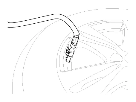
Remove the valve using the valve mounting tool.
|

| 5. |
Apply lubricant to the surface of the valve, and then mount it through
the valve hole of the wheel.
|
| 6. |
Apply soapy water or lubricant to the upper/lower bead section of the
tire.
|
| 7. |
In order to mount lower the beads, place the TPMS sensor at 5 o'clock,
starting from the head of the tire replacement equipment.
|
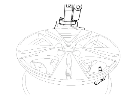
| 8. |
Rotate the rim clockwise and press tire towards 3 o'clock to mount the
lower beads.
|
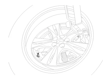
| 9. |
In order to mount the upper beads, press the tire towards 3 o'clock
and turn the rim clockwise.
|
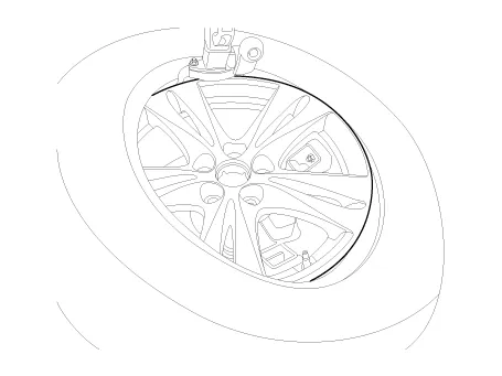
| 10. |
Inject air into the tire until the beads are in the correct position.
|
| 11. |
Adjust the tire pressure according to the recommended tire pressure
for the vehicle.
|
| 12. |
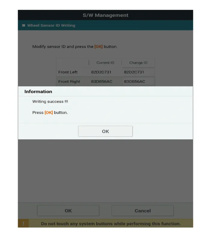
If the TPMS sensor malfunctions, you must perform TPMS sensor learning.
Replace any faulty sensors and perform TPMS sensor learning.
|
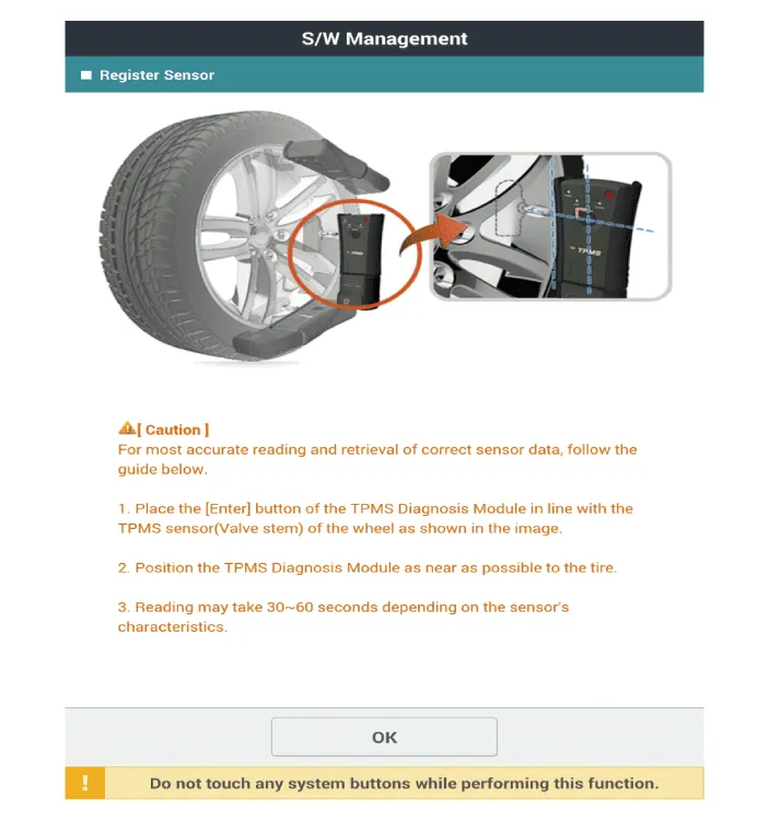
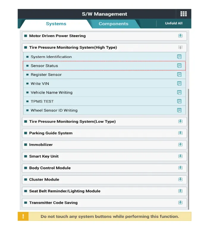
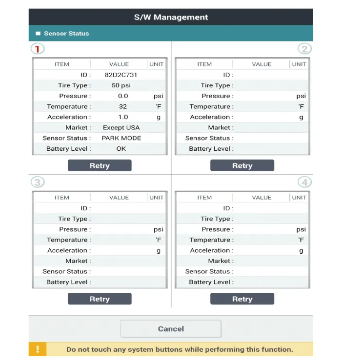
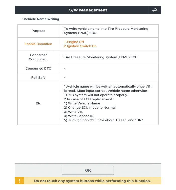
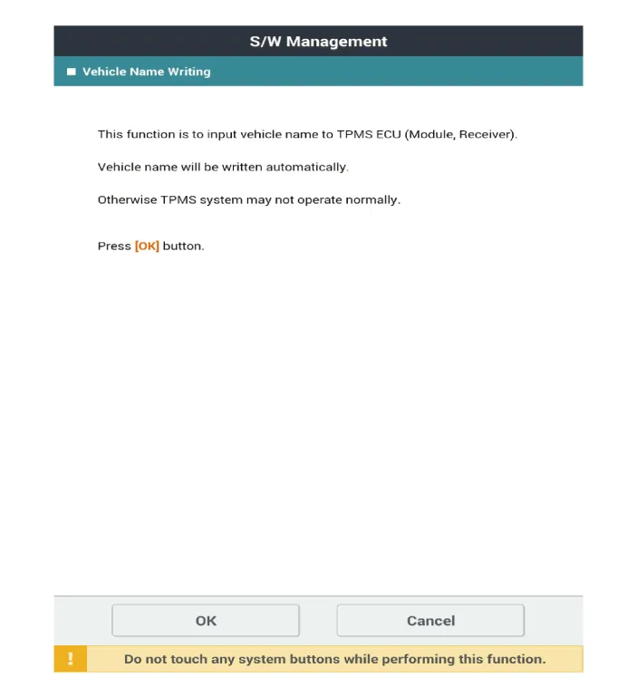
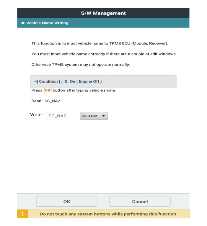
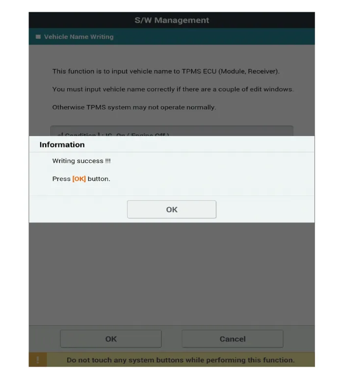
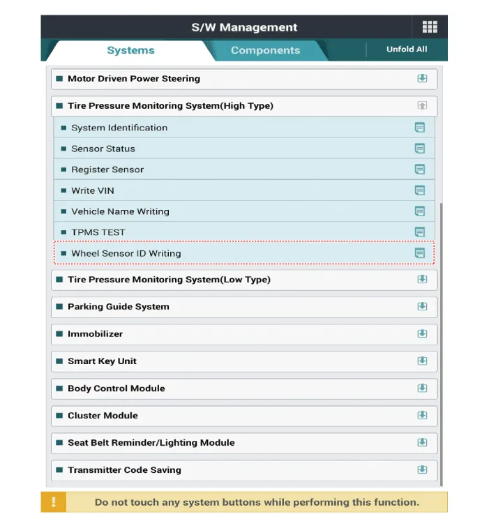
| Diagnostic Procedure Using a Diagnostic Instrument |
| 1. |
Connect the diagnostic instrument to the self-diagnostic connector (16-pin)
beneath the crash pad on the side of driver's seat, and then turn on
the ignition to activate the diagnostic instrument.
|
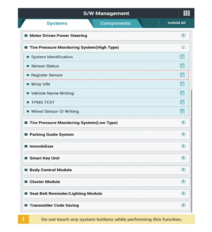
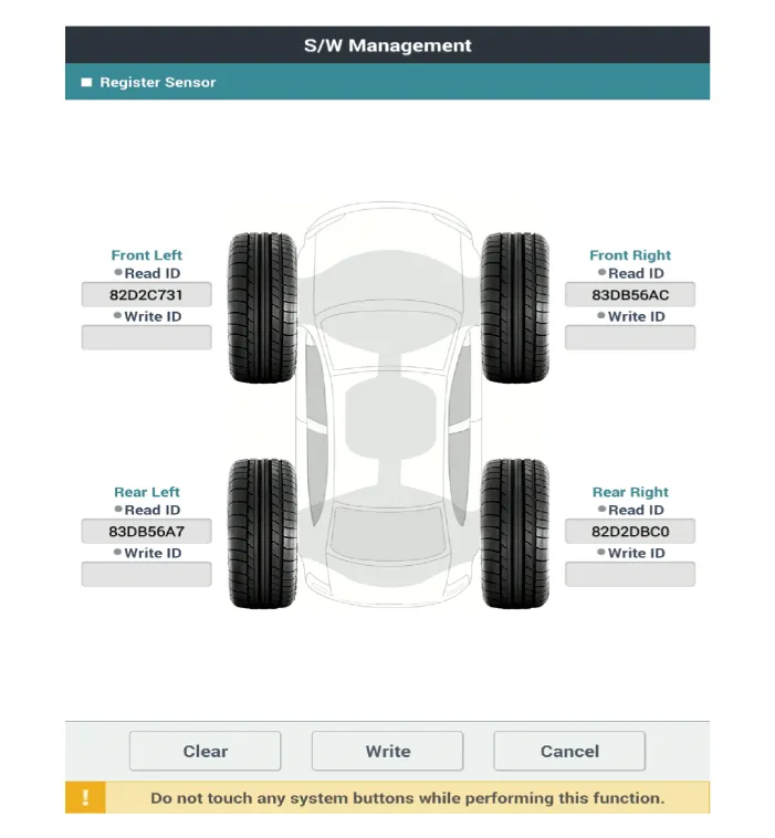
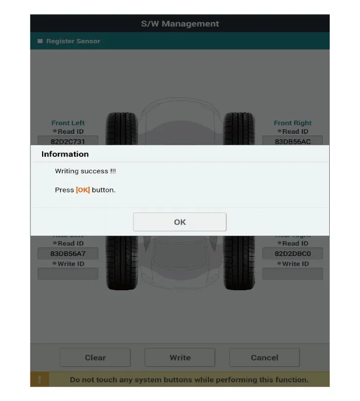
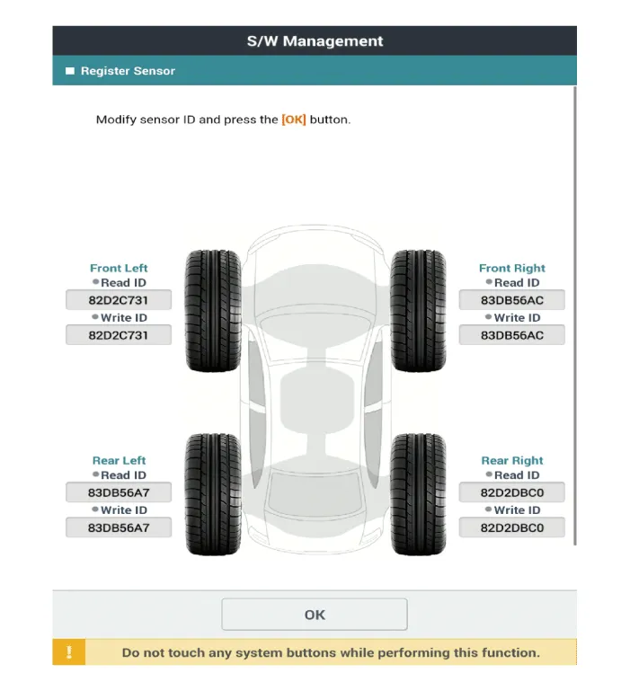
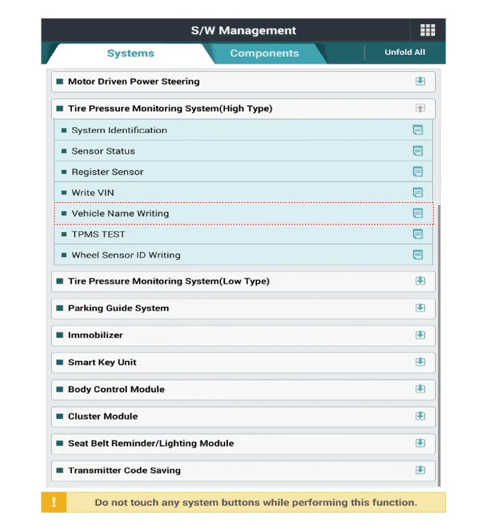
| 2. |
In the GDS Vehicle Type Selection menu, select "Vehicle Type" and "TPMS"
System, and then opt for "OK."
|
|
|
TPMS Receiver. Description and operation
| Description |
| 1. |
Mode
|
| 2. |
Overview
|
| Operation |
| 1. |
General Function
|
| 2. |
General Conditions to Learn New Sensors:
|
| 3. |
General Conditions to Un-Learn a sensor that is removed :
|
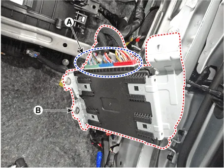
TPMS Receiver. Repair procedures
| Replacement |
| 1. |
Turn the ignition switch OFF and disconnect the battery negative (-)
cable.
|
| 2. |
Remove the glove box.
(Refer to Body - "Glove Box")
|
| 3. |
Disconnect the body control module connectors (A) and then remove the
integrated body control unit (B).
|
| 4. |
Install in the reverse order of removal.
|
| 5. |
After replacing the receiver, learn by using self-diagnostic device
GDS.
|
| Diagnosis procedure by using diagnostic device |
| 1. |
Connect self-diagnosis connector (16 pins) located in the lower driver
side crash pad to self-diagnosis device, and then turn on the self-diagnosis
device after key is ON.
|
| 2. |
Select the "vehicle model" and "TPMS" on GDS vehicle selection screen,
then select OK.
|
Tire. Repair procedures Tire Wear • Using tires and wheel other than the recommended sizes could cause unusual handling characteristics and poor vehicle control, resulting in a serious accident.
Other information:
Hyundai Santa Fe (TM) 2019-2023 Service and Repair Manual: Windshield Wiper/Washer
Components and components location Component Location 1. Windshield wiper arm & blade 2. Wiper & washer switch 3. Windshield washer hose 4. Windshield wiper motor & linkage 5. Washer motor 6.
Hyundai Santa Fe (TM) 2019-2023 Service and Repair Manual: AC Inverter System
Description and operation Description An inverter is a device that transforms the DC voltage from the battery into an AC voltage (220 V). The inverter can power various electrical devices that consume 200 W or less, including mobile phone or notebook rechargers, audio systems, and TVs.
Categories
- Manuals Home
- Hyundai Santa Fe Owners Manual
- Hyundai Santa Fe Service Manual
- Engine Mechanical System
- Front Radar Unit. Repair procedures
- Electronic Parking Brake (EPB)
- New on site
- Most important about car
