Hyundai Santa Fe (TM): Smart Key System / Smart Key Unit. Repair procedures
Hyundai Santa Fe (TM) 2019-2023 Service and Repair Manual / Body Electrical System / Smart Key System / Smart Key Unit. Repair procedures
| Removal |
Integrated Body Control Unit (IBU)
| 1. |
Disconnect the negative (-) battery terminal.
|
| 2. |
Remove the glove box.
(Refer ti Body - "Glove Box")
|
| 3. |
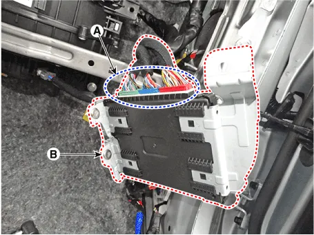
Remove the smart key unit (B) after loosening the mounting bolts(2EA)
and disconnecting the connector (A).
|
| Inspection |
Smart Key Unit
(Refer to Smart Key System - "Smart Key Diagnostic")
Smart Key Switch
(Refer to Smart Key System - "Smart Key Diagnostic")
Antenna
(Refer to Smart Key System - "Smart Key Diagnostic")
| Installation |
Smart Key Unit
| 1. |
Install the smart key unit.
|
| 2. |
Install the smart key unit mounting bolts and connect the connector.
|
| 3. |
Install the driver side crash pad lower panel.
|
| 4. |
Install the negative (-) battery terminal and check the smart key system.
|
Circuit Diagram
Inspection Self Diagnosis With Scan Tool It will be able to diagnose defects of SMART KEY system with diagnostic tool quickly. diagnostic tool can operates actuator forcefully, input/output value monitoring and self diagnosis.
Other information:
Hyundai Santa Fe (TM) 2019-2023 Service and Repair Manual: Fuses And Relays
Components and components location Component Location 1. Engine room relay box 2. Sub relay box 3. ICU Junction block 4. ICM relay box Relay Box (Engine Compartment).
Hyundai Santa Fe (TM) 2019-2023 Service and Repair Manual: Condenser. Components and components location
Categories
- Manuals Home
- Hyundai Santa Fe Owners Manual
- Hyundai Santa Fe Service Manual
- Blower
- Rear Disc Brake. Repair procedures
- Auto Hold. Warning messages
- New on site
- Most important about car

Copyright © 2026 www.hsafe4.com - 0.0172