Hyundai Santa Fe (TM): Driveshaft and axle / Rear Axle Assembly
Components and components location
| Components |
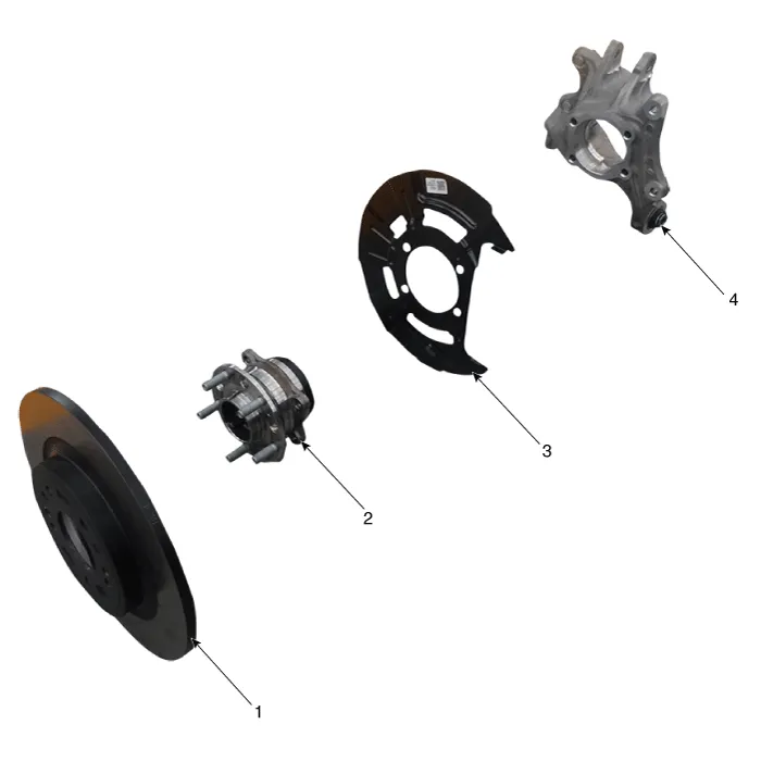
| 1. Rear brake
disc 2. Rear hub assembly |
3. Dust cover 4. Rear carrier assembly |
Repair procedures
| Removal |
|

| 1. |
Loosen the wheel nuts slightly.
Raise the vehicle, and make sure it is securely supported.
|
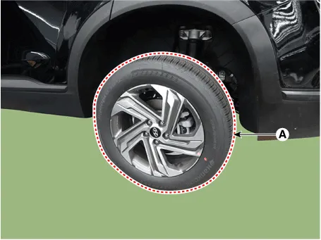
| 2. |
Remove the rear wheel and tire (A) from rear hub.
|

| 3. |
Remove the rear brake caliper.
(Refer to Brake System - "Rear Disc Brake")
|
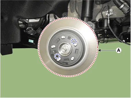
| 4. |
Loosen the screw and then removing the rear brake disc (A).
|
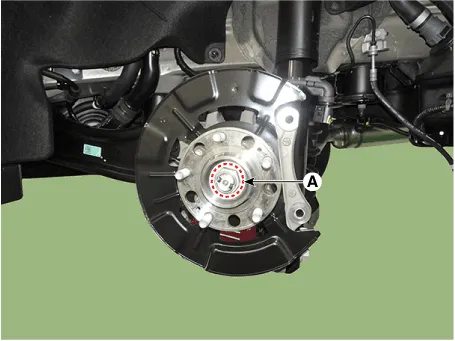
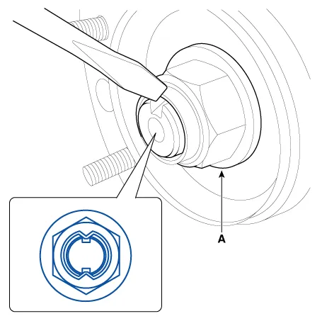
| 5. |
Loosen the driveshaft caulking nut (A) from the rear hub.
|
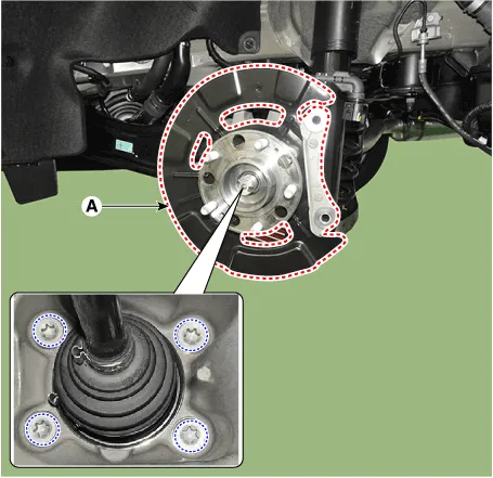
| 6. |
Remove the rear hub assembly and dust cover (A) after loosening the
mounting bolts.
|
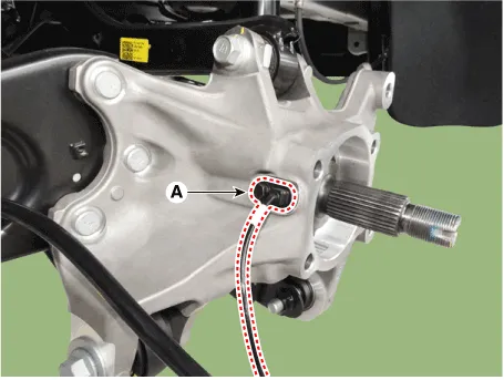
| 7. |
Remove the rear wheel speed sensor (A) after loosening the mounting
bolt.
|
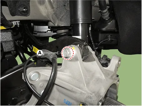
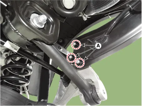
| 8. |
Remove the rear upper arm from the rear carrier after loosening the
bolt and nut (A).
|
| 9. |
Remove the trailing arm from the rear carrier after loosening the mounting
nuts (A).
|
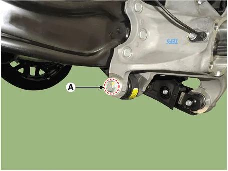
| 10. |
Remove the rear assist arm from the rear carrier after loosening the
bolt and nut (A).
|
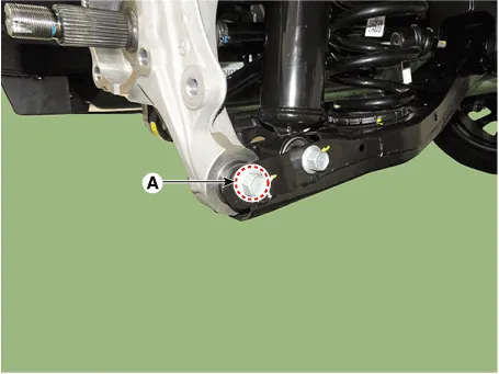
| 11. |
Remove the rear lower arm from the rear carrier after loosening the
bolt and nut (A).
|
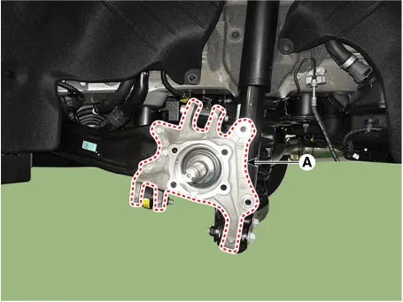
| 12. |
Remove the rear carrier (A).
|
| Inspection |
| 1. |
Check the hub for cracks and the splines for wear.
|
| 2. |
Check the rear axle carrier for cracks.
|
| 3. |
Replace only the sensor cap when the warning light turns on due to a
defective sensor cap of the hub bearing.
(Refer to Brake System - "Rear Wheel Speed Sensor")
|
| Installation |
| 1. |
To install, reverse the removal procedures.
|
| 2. |
Check the alignment.
(Refer to Suspension System - "Alingment")
|
Front Driveshaft. Components and components location Components 1. Front driveshaft (LH) 2. Inner shaft bearing bracket 3.
Components and components location Components 1. Rear drive shaft (left) 2. Rear drive shaft (right) Repair procedures Removal • Be careful not to damage the parts located under the vehicle (floor under cover, fuel filter, fuel tank and canister) when raising the vehicle using the lift.
Other information:
Hyundai Santa Fe (TM) 2019-2023 Service and Repair Manual: Heater
Heater Unit. Components and components location Component Location 1. Heater Unit Assembly Components 1. Heater unit assembly 2. Heater NVH pad 3. Heater seal duct 4.
Hyundai Santa Fe (TM) 2019-2023 Service and Repair Manual: Components and components location
Categories
- Manuals Home
- Hyundai Santa Fe Owners Manual
- Hyundai Santa Fe Service Manual
- Front Radar Unit. Repair procedures
- Hydraulic System
- Tire Pressure Monitoring System (TPMS)
- New on site
- Most important about car
