Hyundai Santa Fe (TM): Engine Control System / Crankshaft Position Sensor (CKPS). Repair procedures
| Inspection |
| 1. |
Check the signal waveform of the CMPS and CKPS using the diagnostic
tool.
|
| Removal |
|

| 1. |
Turn the ignition switch OFF and disconnect the battery negative (-)
cable.
|
| 2. |
Disconnect the crankshaft position sensor connector (A).
|

| 3. |
Lift the vehicle.
|
| 4. |
Remove the engine room under cover.
(Refer to Engine Mechanical System - "Engine Room Under Cover")
|
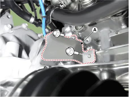
| 5. |
Remove the protector (A).
|
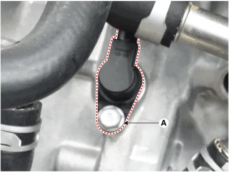
| 6. |
Remove the installation bolt (A), and then remove the crankshaft position
sensor.
|
| Installation |
|
|
|
| 1. |
Installation is reverse of removal.
|
Circuit Diagram Harness Connector
Description Camshaft Position Sensor (CMPS) is a hall sensor and detects the camshaft position by using a hall element. It is related with Crankshaft Position Sensor (CKPS) and detects the piston position of each cylinder which the CKPS can't detect.
Other information:
Hyundai Santa Fe (TM) 2019-2023 Service and Repair Manual: Photo Sensor. Description and operation
Description The photo sensor is located at the center of the defrost nozzles. The photo sensor contains a photovoltaic (sensitive to sunlight) diode. The solar radiation received by its light receiving portion, generates an electromotive force in proportion to the amount of radiation received which is transferred to th
Hyundai Santa Fe (TM) 2019-2023 Service and Repair Manual: Auto Defogging Sensor. Repair procedures
Inspection To inspect and diagnose the sensor, refer to Self-Diagnosis procedure and DTC guide. Replacement 1. Disconnect the negative (-) battery terminal. 2. Remove the rain sensor inner cover (A) and rain sensor cover (B).
Categories
- Manuals Home
- Hyundai Santa Fe Owners Manual
- Hyundai Santa Fe Service Manual
- Engine Electrical System
- Electronic Parking Brake (EPB)
- Tire Pressure Monitoring System (TPMS)
- New on site
- Most important about car
