Hyundai Santa Fe (TM): Engine Control System / Camshaft Position Sensor (CMPS). Repair procedures
| Inspection |
| 1. |
Check the signal waveform of the CMPS and CKPS using the diagnostic
tool.
|
| Removal |
|

| 1. |
Turn the ignition switch OFF and disconnect the battery negative (-)
cable.
|
| 2. |
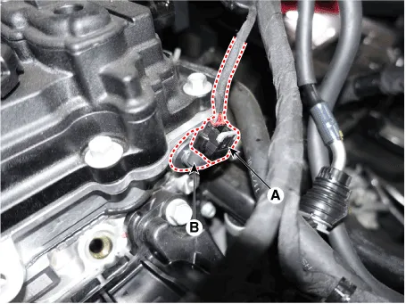
Disconnect the camshaft position sensor connector (A).
|
| 3. |
Remove the installation bolt, and then remove the sensor (B).
|
| 1. |
Turn the ignition switch OFF and disconnect the battery negative (-)
cable.
|
| 2. |
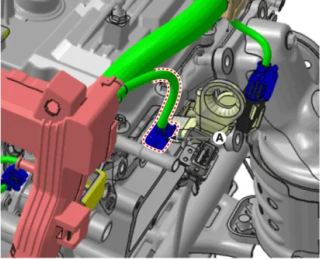
Disconnect the camshaft position sensor connector (A).
|
| 3. |
Remove the hanger and the protector.
|
| 4. |
Remove the installation bolt, and then remove the sensor.
|
| Installation |
|

|
|
|
| 1. |
Installation is reverse of removal.
|
Circuit Diagram Harness Connector
Description Knocking is a phenomenon characterized by undesirable vibration and noise and can cause engine damage. Knock Sensor (KS) is installed on the cylinder block and senses engine knocking.
Other information:
Hyundai Santa Fe (TM) 2019-2023 Service and Repair Manual: In-car Sensor. Description and operation
Description The In-car air temperature sensor is built in the heater & A/C control unit. The sensor consists of a thermistor that measures the inside temperature. The signal decided by the resistance value that changes in accordance with perceived inside temperature, is delivered to heater control unit, and according t
Hyundai Santa Fe (TM) 2019-2023 Service and Repair Manual: Rear View Monitor (RVM)
Description and operation Description Back view camera will activate when the backup light is ON with the ignition switch ON and the shift lever in the R position. This system is a supplemental system that shows behind the vehicle through the H/UNIT or the ECM (Reverse Display Room Mirror) mirror while backing-up.
Categories
- Manuals Home
- Hyundai Santa Fe Owners Manual
- Hyundai Santa Fe Service Manual
- Rear seats
- Emission Control System
- Restraint
- New on site
- Most important about car
