Hyundai Santa Fe (TM): Brake System / Brake Line. Repair procedures
| Removal |
|

| 1. |
Disconnect the brake fiuid level switch connector, and remove the reservoir
cap.
|
| 2. |
Remove the brake fluid from the master cylinder reservior with a syringe.
|
| 3. |
Remove the brake tube after loosening the flare nuts from the ESP, master
cylinder and brake tube connector.
|
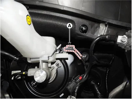
| 1. |
Disconnect the brake fluid level sensor connector (A).
|
| 2. |
Remove the brake fluid from the master cylinder reservoir with a syringe.
|

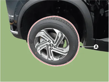
| 3. |
Remove the wheel & tire.
|
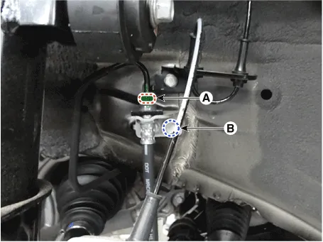
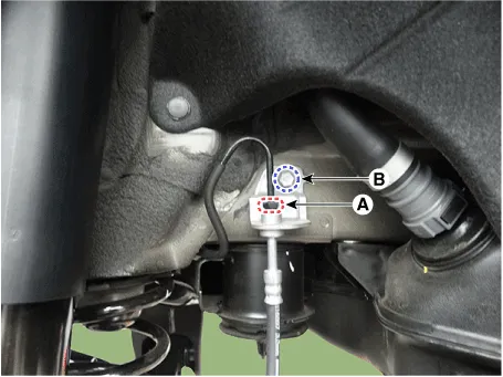
| 4. |
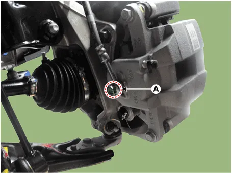
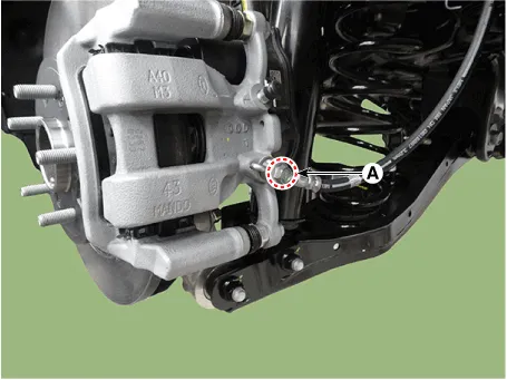
Remove the tube flare nut (A) and brake hose bracket bolt (B).
[Front]
[Rear]
|
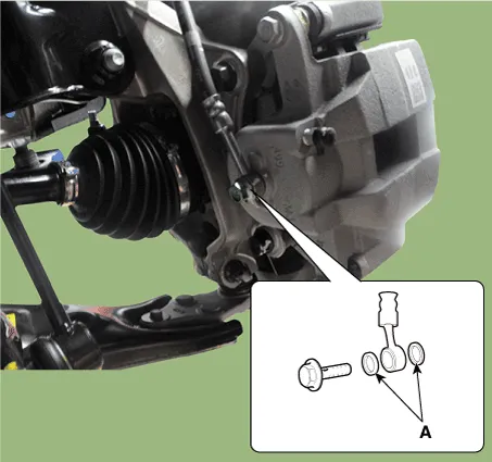
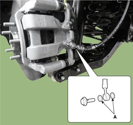
| 5. |
Remove the hose after loosening the brake hose bolt (A) from the caliper.
[Front]
[Rear]
|
| Inspection |
| 1. |
Check the brake tubes for cracks, crimps and corrosion.
|
| 2. |
Check the brake tube flare nuts for damage and fluid leakage.
|
| Installation |
| 1. |
To install, reverse the removal procedures.
|
| 2. |
After installation, bleed the brake system.
(Refer to Brake System - "Brake System Bleeding")
(Refer to Brake System - "ESP System Bleeding)
|
Specification Fluid Type DOT 4 Reservoir Quantity (cc) MAX LEVEL A + B + C + D 493 ± 20 ON LEVEL B + C + D 206 ± 20 MIN LEVEL - 167 PARTIAL LEVEL C Pri : 63 D Sec : 49 CLUTCH LEVEL E -
Other information:
Hyundai Santa Fe (TM) 2019-2023 Service and Repair Manual: Indicators And Gauges
Troubleshooting Troubleshooting Symptom Possible cause Remedy Speedometer does not operate Cluster fuse (10A) blown Check for short and replace fuse Speedometer faulty Check speedometer CAN line faulty
Hyundai Santa Fe (TM) 2019-2023 Service and Repair Manual: Specifications
Specification Air Conditioner Item Specification Compressor Type 7HVe17 Oil type & Capacity Single (Front only) FD46XG(IDMITSU) 100± 10cc (3.
Categories
- Manuals Home
- Hyundai Santa Fe Owners Manual
- Hyundai Santa Fe Service Manual
- Rear seats
- Engine Mechanical System
- Engine Control/Fuel System
- New on site
- Most important about car
