Hyundai Santa Fe (TM): Steering System / Steering wheel
Hyundai Santa Fe (TM) 2019-2023 Service and Repair Manual / Steering System / Steering wheel
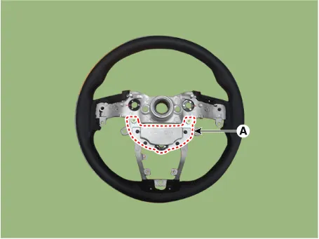
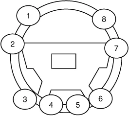
Components and components location
| Components |
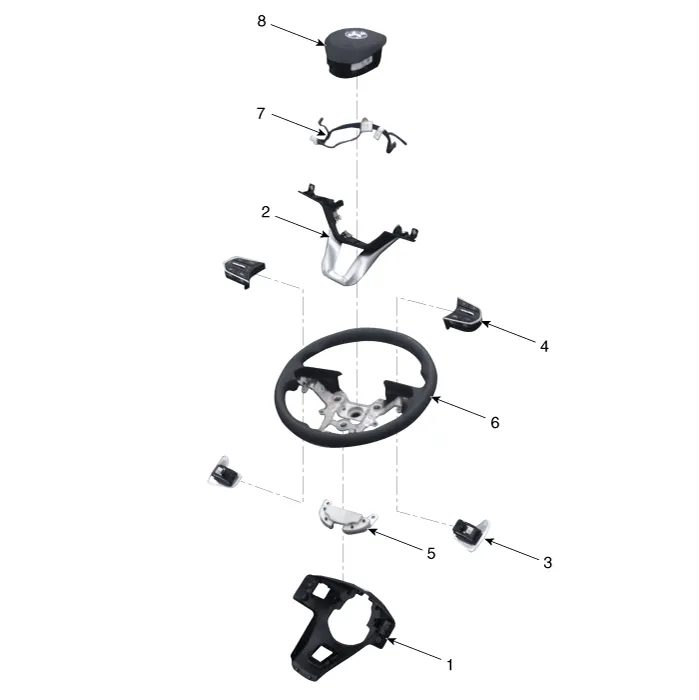
| 1. Lower cover 2. Switch bezel 3. Remote control switch 4. Paddle shift |
5. Damper 6. Steering Wheel 7. Wiring 8. Drive airbag module (DAB) |
Repair procedures
| Removal |
| 1. |
Turn the steering wheel so that the front wheels can face straight ahead.
|
| 2. |
Turn the ignition switch OFF and disconnect the battery negative (-)
cable.
|
| 3. |
Remove the drive airbag module.
(Refer to Restraint - "Drive Air Bag Module")
|
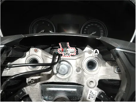
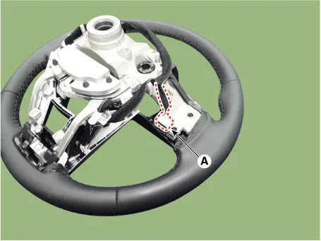
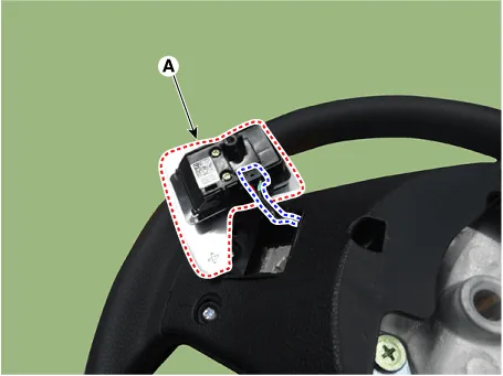
| 4. |
Disconnect the steering wheel connector (A).
|
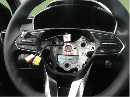
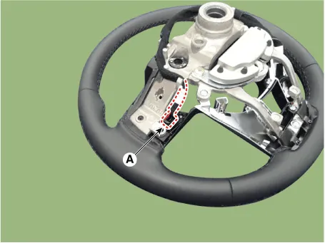
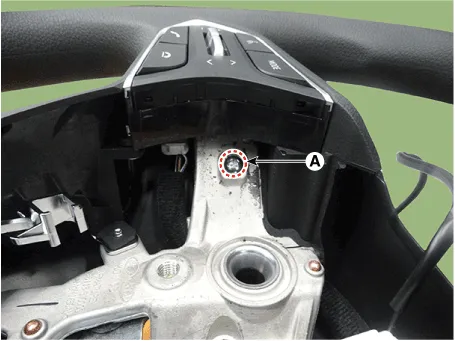
| 5. |
Remove the steering wheel after loosening the bolt (A).
|

| Disassembly |
[Non-Paddle Shift Type]
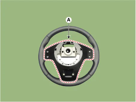
| 1. |
Loosen the screw and then remove the lower cover (A).
|
| 2. |
Disconnect the remote control switch connector (A).
|
| 3. |
Loosen the screw and then remove the remote control switch (A).
|
| 4. |
Remove the steering wheel bezel (A).
|
| 5. |
Remove the steering wheel damper (A) after loosening the mounting bolts.
|
[Paddle Shift Type]
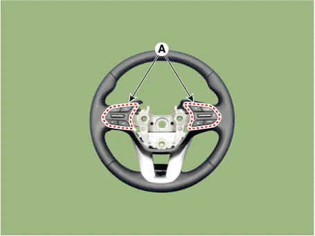
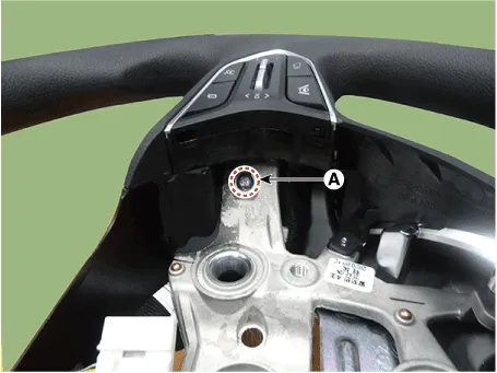
| 1. |
Loosen the paddle shift switch mounting screw (A).
|
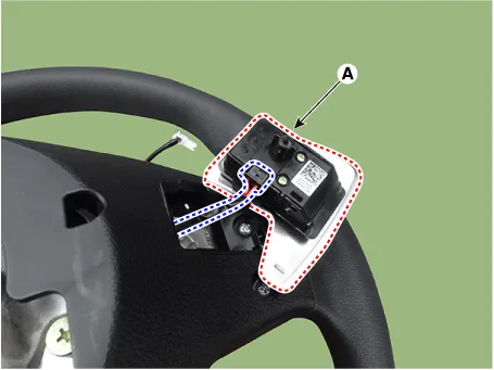
| 2. |
Remove the paddle shift switch (A) after disconnecting the connector.
|
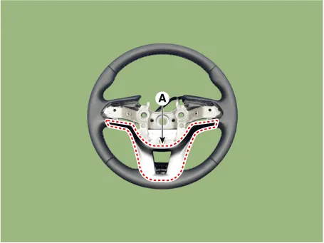
| 3. |
Remove the lower cover (A) after loosening the screw.
|
| 4. |
Disconnect the remote control switch connector (A).
|
| 5. |
Remove the remote control switch (A) after loosening the screw.
|
| 6. |
Remove the steering wheel bezel (A).
|
| 7. |
Remove the steering wheel damper (A) after loosening the mounting bolts.
|
| Reassembly |
| 1. |
To reassembly, reverse the disassembly procedure.
|
| Installation |
| 1. |
To install, reverse the removal procedures.
|
Heated Steering wheel. Description and operation
| Description |
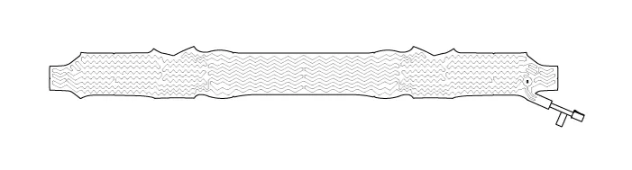
Heated pads to grip the steering grip makes the fever.
Heated pad
Heated Steering wheel. Specifications
| Specifications |
|
Item |
Specification |
|
Voltage |
13.5 V |
|
Heated pad resistance |
1.68 Ω ± 10 % |
|
NTC resistance |
10.0 kΩ ± 5 % (25 °C) |
Heated Steering wheel. Schematic diagrams
| System Circuit Diagram |
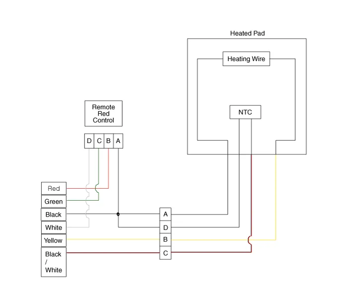

Terminal Function
|
Item |
Pin |
Function |
Wire color |
|
Pad |
A |
HEATER |
Red / Black |
|
B |
GND |
Brown / Black |
|
|
C |
NTC- |
Black |
|
|
D |
NTC+ |
Black |
|
|
Remote control |
A |
GND |
Black |
|
B |
BAT |
Red |
|
|
C |
LED |
Green |
|
|
D |
SWITCH |
White |
Heated Steering wheel. Repair procedures
| Inpection |
| 1. |
Measure a resistance of NTC and Heated pad.
|
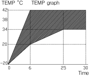
| 2. |
Measure a temperature.
|
Service Adjustment Procedure Steering Wheel Play Inspection 1. Turn the steering wheel so that the front wheels can face straight ahead.
Other information:
Hyundai Santa Fe (TM) 2019-2023 Service and Repair Manual: Description and operation
Hyundai Santa Fe (TM) 2019-2023 Service and Repair Manual: Parking Distance Warning (PDW)
Description and operation Description • PDW consists of 8 sensors (front : 4 units, rear : 4 units) that are used to detect obstacles and transmit the result in three separate warning levels, the first, second and third to IBU via LIN communication.
Categories
- Manuals Home
- Hyundai Santa Fe Owners Manual
- Hyundai Santa Fe Service Manual
- Engine Control/Fuel System
- Auto Hold. Warning messages
- Automatic Transaxle Control System
- New on site
- Most important about car

Copyright © 2026 www.hsafe4.com - 0.0142