Hyundai Santa Fe: Differential Carrier Assembly / Repair procedures
Hyundai Santa Fe (TM) 2019-2025 Service Manual / Driveshaft and axle / Differential Carrier Assembly / Repair procedures
| Removal |
|

| 1. |
Disconnect the (-) battery terminal.
|
| 2. |
Remove the rear driveshaft.
(Refer to Rear Driveshaft Assembly - "Rear Driveshaft")
|
| 3. |
Remove the propeller shaft.
(Refer to Propeller Shaft Assembly - "Propeller Shaft")
|
| 4. |
Remove the coupling assembly.
(Refer to All Wheel Drive (AWD) System - "Direct Electro Hydraulic Actuator
Coupling")
|
| 5. |
Install a jack on the lower part of the differential.
|
| 6. |
Remove the differential carrier assembly (A) after loosening the mounting
bolts.
|
| 7. |
Remove the differential carrier bracket (A) after loosening the mounting
bolts.
|
| Inspection |
| 1. |
After clearing, check for damage parts or abrasion. Follow the below
method, if any are noticed.
|
||||||||||||||||||
| 2. |
Check the tooth contact pattern.
|
||||||||||||||||||||||||||||


| Disassembly |
Differential gear assembly
| 1. |
Remove the drain plug packing (A) and drain plug (B) to drain the gear
oil.
|
| 2. |
Loosen the differential side cover mounting bolts.
|
| 3. |
Widen the gap between the side cover and the case to remove the side
cover (A).
|
| 4. |
Remove the differential gear assembly (A).
|
| 5. |
Remove the ring gear (A) from the gear carrier after loosening the mounting
bolts.
|
| 6. |
Remove the differential gear bearing (A) using the SST (09501-C9200)
and puller.
[Differential carrier cover side]
[Differential carrier side]
|
Pinion drive gear assembly
| 1. |
Fix the differential carrier assembly using the SST (09501-C9230, 0K530-P2500,
0K501-P2232).
|
| 2. |
Loosen the pinion gear lock nut using the SST (09501-C9230).
|
| 3. |
Remove the pinion drive gear assembly (A).
|
| 4. |
Remove the spacer (A) from the pinion drive gear assembly.
|
| 5. |
Install the SST (09501-C9310, 09452-2E000) and remove the bearing from
the pinion drive gear using a press.
|
| 6. |
Remove the pinion inner bearing adjustment shim (A) from the pinion
drive gear.
|
Differential carrier case
| 1. |
Remove the pinion oil seal (A).
|
| 2. |
Remove the outer pinion bearing (A).
|
| 3. |
Remove the outer pinion bearing race (A) using the SST (09501-C9140,
09501-C9320).
|
| 4. |
Remove the inner pinion bearing race (A) using the SST (09501-C9140,
09501-C9330).
|
| 5. |
Remove the differential carrier case side oil seal (A).
|
| 6. |
Remove the differential carrier case side bearing race (A) and adjustment
shim (B).
|
| 7. |
Remove the filler gasket (A) and filler plug (B) from the differential
carrier case side cover.
|
| 8. |
Remove the differential carrier case side cover oil seal (A).
|
| 9. |
Remove the differential carrier case side cover bearing race (A) and
adjustment shim (B).
|
| Reassembly |
Pinion drive gear assembly
| 1. |
Install the inner pinion bearing adjustment shim (A) on the pinion drive
gear assembly.
|
| 2. |
Install the inner pinion bearing (A) on the pinion drive gear using
SST (0K530-P2200) and press.
|
| 3. |
Install the spacer (A) in the pinion drive gear assembly.
|
Differential gear assembly
| 1. |
Install the ring gear (A) on the gear carrier.
|
| 2. |
Install the differential gear bearings (A) on both sides using the SST
(0K530-P2300) and press.
|
Differential carrier case
| 1. |
Install the differential carrier case side cover bearing adjustment
shim (A) and race (B).
|
| 2. |
Install the differential carrier case side bearing adjustment shim (A)
and race (B).
|
| 3. |
Hold the differential carrier assembly using the SST (09501-C9231, 0K530-P2500,
0K501-P2232).
|
| 4. |
Install the outer, inner pinion bearing race using SST (09501-C9340).
|

| 5. |
Install the pinion drive gear assembly (A).
|
| 6. |
Install outer pinion bearing (A) on pinion gear assembly.
|
| 7. |
Place the SST (0K530-P2200) on the pinion gear spline side and press
the bearing (A) of the until the thread can engages the lock nut.
|
| 8. |
Pre-tighten the pinion lock nut (A) to the thread on the side of the
pinion gear spline.
|
| 9. |
Fix the lock nut using the SST (0K530-P2500).
|
| 10. |
Tighten the pinion gear lock nut using SST (09501-C9231) to press the
outer bearing.
|
| 11. |
Remove the SST (0K530-P2500).
|
| 12. |
Press the pinion oil seal using SST (0K530-P2100, 09231-H1100).
|
| 13. |
Install the differential gear assembly (A) in the differential carrier
case.
|
| 14. |
Install the differential carrier case side cover (A).
|
| 15. |
Install SST (0K530-P2400) on the pinion drive gear spline side and set
the dial gauge on the case.
|
| 16. |
After moving the SST (0K530-P2400) left and right, read the dial gauge
and measure the backlash.
|
| 17. |
Measure the total preload.
|
| 18. |
Loosen the bolt and remove the differential carrier case side cover
(A).
|
| 19. |
Apply the sealant on the adhesive side between differential carrier
case and side cover.
|
| 20. |
Install the differential case side cover (A).
|
| 21. |
Install the oil seal on both sides of the differential carrier case
using the SST (09501-C9190, 09231-H1100).
|
| 22. |
Install the drain plug packing (A) and drain plug (B) on the differential
carrier case.
|
| 23. |
Add new gear oil through filler plug hole (A).
|
| 24. |
Install the filler plug (A) and filler gascket (B).
|
| Installation |
| 1. |
Install the differential carrier bracket (A).
|
| 2. |
Install the jack and intall the differential carrier assembly (A).
|
| 3. |
Install the coupling assembly.
(Refer to All Wheel Drive (AWD) System - "Direct Electro Hydraulic Actuator
Coupling")
|
| 4. |
Install the propeller shaft.
(Refer to Propeller Shaft Assembly - "Propeller Shaft")
|
| 5. |
Install the rear driveshaft.
(Refer to Rear Driveshaft Assembly - "Rear Drive Shaft")
|
| 6. |
Connect the (-) battery terminal.
|
| 7. |
Check the rear alignment.
(Refer to Suspension System - "Alignment")
|
 Components and components location
Components Location
1. Rear differential
carrier assembly
2. Rear driveshaft assembly
3. Coupling Assembly
4...

Other information:
Hyundai Santa Fe (TM) 2019-2025 Service Manual: Heater & A/C Control Unit (Rear). Repair procedures
Replacement • When removing with a flat-tip screwdriver or remover, wrap protective tape around the tools to prevent damage to components...
Hyundai Santa Fe (TM) 2019-2025 Owner's Manual: Air cleaner
Filter replacement The air cleaner filter can be cleaned for inspection using compressed air. Do not attempt to wash or to rinse it, as water will damage the filter. If soiled, the air cleaner filter must be replaced. 1. Pull up the air cleaner filter cover (1)...
Categories
- Manuals Home
- 4th Generation Santa Fe Owners Manual
- 4th Generation Santa Fe Service Manual
- Resetting the power liftgate
- Smart liftgate
- Child-protector rear door locks
- New on site
- Most important about car
Armrest
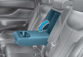
The armrest is located in the center of the rear seat. Pull the armrest down from the seatback to use it.

Copyright © 2025 www.hsafe4.com