Hyundai Santa Fe (TM): Heating,Ventilation And Air Conditioning / Rear Heater
Rear Heater Unit. Components and components location
| Component Location |
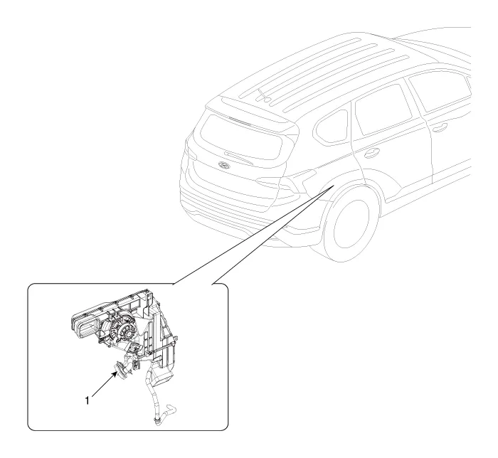
| 1. Rear Heater
& A/C Unit |
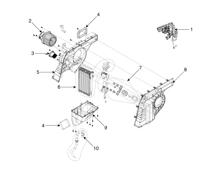
| Components |
|
1. Rear heater & blower unit assembly 2. Blower motor assembly 3. Rear power mosfet 4. Duct seal guide 5. Evaporator case [LH] |
6. Evaporator core assembly 7. Evaporator pipe assembly 8. Evaporator case [RH] 9. Evaporator lower case 10. Drain hose assembly |
Rear Heater Unit. Repair procedures
| Replacement |
|

| 1. |
Disconnect the negative (-) battery terminal.
|
| 2. |
Recover the refrigerant with a recovery/charging station.
|
| 3. |
Remove the luggage side trim [RH]
(Refer to Body - "Luggage Side Trim")
|
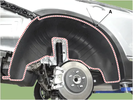
| 4. |
Loosen the mounting screws and separate the rear wheel guard [RH] (A).
|
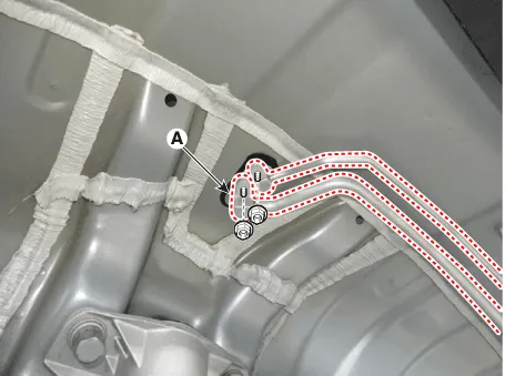
| 5. |
Loosen the mounting nuts and remove the refrigeration line (A).
|

| 6. |
Loosen the rear evaporator pipe mounting bolts.
|
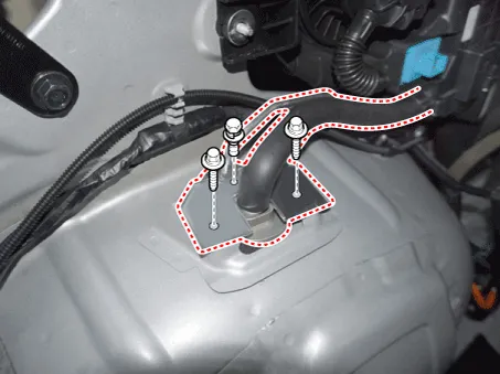
| 7. |
Remove the mounting bolts and remove the rear A/C duct (A).
|

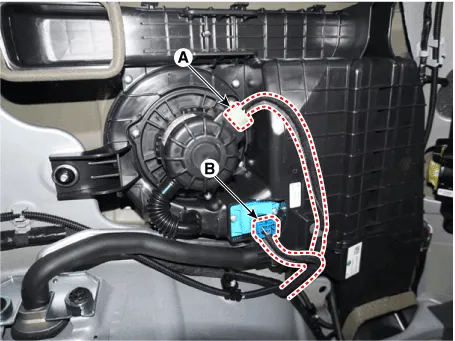
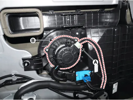
| 8. |
Separate the rear blower motor connector (A) and rear mosfet connector
(B).
|
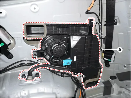
| 9. |
Loosen the mounting bolts and nuts and remove the A/C unit (A).
|
| 10. |
Install in the reverse order of removal.
|
Rear Evaporator Core. Repair procedures
| Replacement |
| 1. |
Remove the rear heater & A/C unit.
(Refer to Rear Heater - "Rear Heater Unit")
|
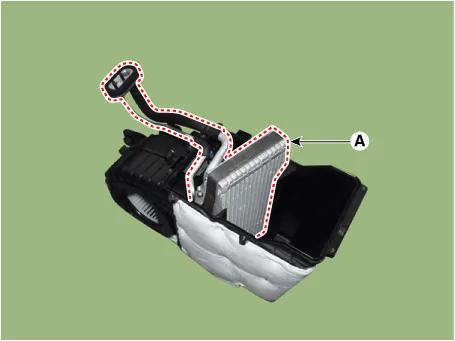
| 2. |
Loosen the mounting screws and remove the rear A/C lower case (A).
|

| 3. |
Remove the rear evaporator core (A).
|
| 4. |
Install in the reverse order of removal.
|
Rear Blower Motor. Repair procedures
| Replacement |
| 1. |
Disconnect the negative (-) battery terminal.
|
| 2. |
Remove the luggage side trim [RH].
(Refer to Body - "Luggage Side Trim")
|
| 3. |
Separate the blower motor connector (A) and loosen the mounting screws
and remove the blower motor (B).
|
| 4. |
Install in the reverse order of removal.
|
Rear Power Mosfet. Repair procedures
| Inspection |
| 1. |
Turn the ignition switch ON.
|
| 2. |
Manually operate the control switch and measure the voltage of the blower
motor.
|
| 3. |
Select the control switch to raise the voltage until it reaches high
speed.
Specification
|
| 4. |
If the measured voltage is not within specification, substitute with
a known-good power mosfet and check for proper operation.
|
| 5. |
Replace the power mosfet if it is proved that there is a problem with
it.
|
| Replacement |
| 1. |
Disconnect the negative (-) battery terminal.
|
| 2. |
Remove the luggage side trim [RH].
(Refer to Body -"Luggage Side Trim")
|
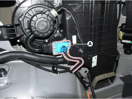
| 3. |
Separate the connector and loosen the mounting screw ,remove the power
mosfet (A).
|
| 4. |
Install in the reverse order of removal.
|
Blower Unit. Components and components location Components Location 1. Blower unit assembly Components 1.
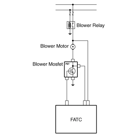
Heater & A/C Control Unit (Manual). Components and components location Component Connector Pin Function Pin No Connector A Connector B 1 Battery Low 2 ISG B+ Common 3 ILL+ (TAIL) Ground 4 Sensor REF (+5V) Middle Low 5 Mode Actuator Feedback Middle High 6 Temperature Actuator Feedback High 7 Intake Actuator Feedback - 8 Evaporator Temperature Sensor (+) 9 Ambient Temperature Sensor (+) 10 Mode Actuator (Vent) 11 Mode Actuator (Defrost) 12 Temperature Control Actuator (Cool) 13 Temperature Control Actuator (Warm) 14 Intake Actuator (Fresh Air) 15 Intake Actuator (Recirculated Air) 16 HTD (Rear Defrost) 17 Rear Defogging Swich 18 Rear C-LINE 19 Blower Common Signal 20 ILL - (RHEO) 21 IGN2 22 IGN1 23 - 24 Rear Blower Motor (+) 25 Rear Mosfet (GATE) 26 Rear Mosfet (DRAIN F/B) 27 Max Blower on Signal 28 PTC Relay 2 (DIESEL) PTC Relay 1 (GASOLINE) 29 - 30 PTC ON Signal (DIESEL) - (GASOLINE) 31 - 32 - 33 P-CAN_(HIGH) 34 P-CAN_(LOW) 35 - 36 ECV (+) 37 ECV (-) 38 Sensor Ground 39 Ground 40 Ground Heater & A/C Control Unit (Manual).
Other information:
Hyundai Santa Fe (TM) 2019-2023 Service and Repair Manual: Seat Electrical
Components and components location Component Location 1. Lumber support motor (Vertical) 2. Lumbar support motor (Horizontal) 3. Reclining motor 4. Rear height motor 5. Front height motor 6. Slide motor 7.
Hyundai Santa Fe (TM) 2019-2023 Service and Repair Manual: Parking Distance Warning (PDW)
Description and operation Description • PDW consists of 8 sensors (front : 4 units, rear : 4 units) that are used to detect obstacles and transmit the result in three separate warning levels, the first, second and third to IBU via LIN communication.
Categories
- Manuals Home
- Hyundai Santa Fe Owners Manual
- Hyundai Santa Fe Service Manual
- Engine Electrical System
- Front Radar System
- Engine Mechanical System
- New on site
- Most important about car
