Hyundai Santa Fe (TM): Body Electrical System / Power Windows
Description and operation
| Function Of Safety Power Window |
| 1. |
Safety function condition
When detect the force of 100N (using the 10N/mm spring) during the window
rising, window is reversed.
|
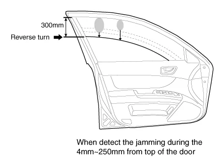
| 2. |
Length of window reversing (except holding the auto-up switch)
|

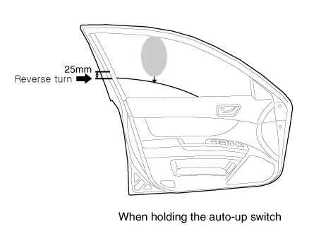
| 3. |
Length of window reversing (holding the auto-up switch)
|
| 4. |
Safety function is not available area
Safety function is not available during the 4mm from top of the door.
|
| 1. |
Initializing of Battery Connection
When the battery power is removed for over 5 minutes, safety power window
switch need the initializing.
|
| 2. |
Initializing of fail safe mode
|
Components and components location
| Component Location |
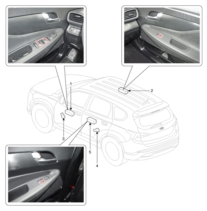
| 1. DAU (Door
Area Unit) 2. Assist window switch 3. Front window motor |
4. Rear window
motor 5. Rear window switch |
Power Window Motor. Components and components location
| Components |
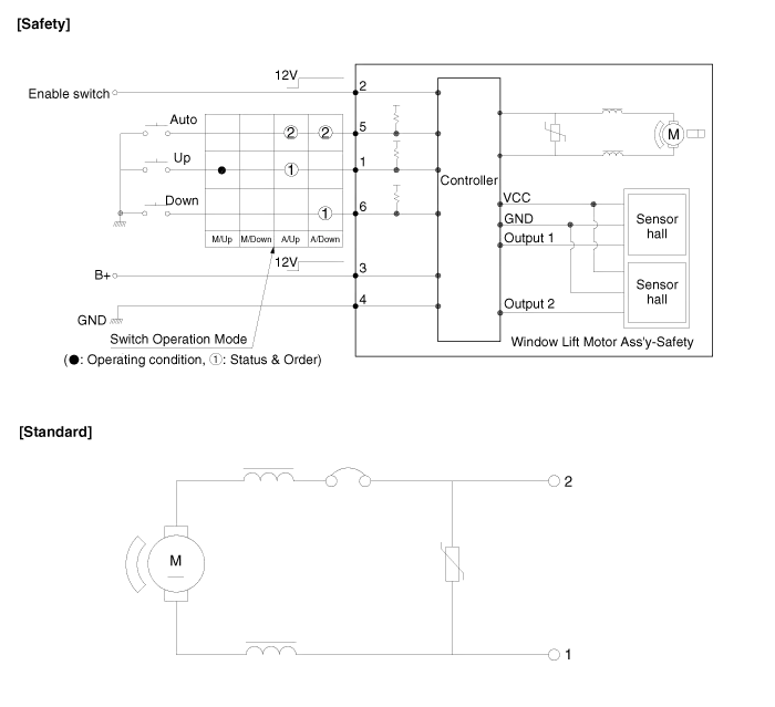
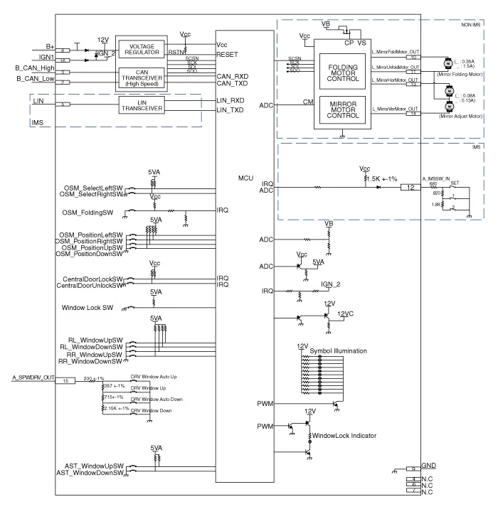
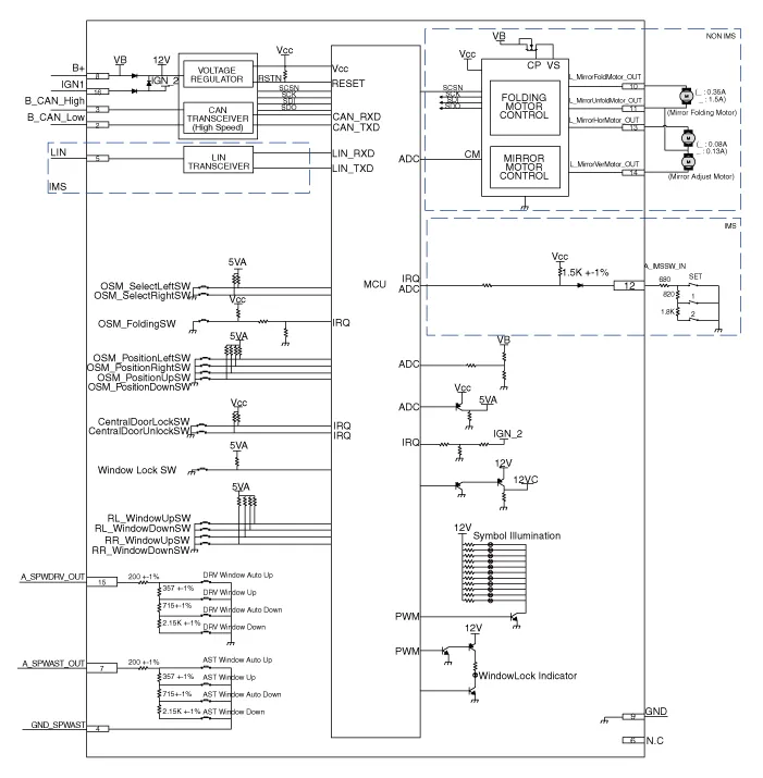
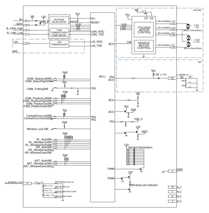
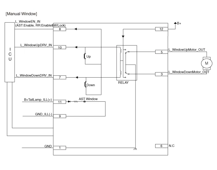
Power Window Motor. Schematic diagrams
| Circuit Diagram |
Power Window Motor. Repair procedures
| Inspection |
| 1. |
Disconnect the negative (-) battery terminal.
|
| 2. |
Remove the front door trim.
(Refer to Body - "Front Door Trim")
|
| 3. |
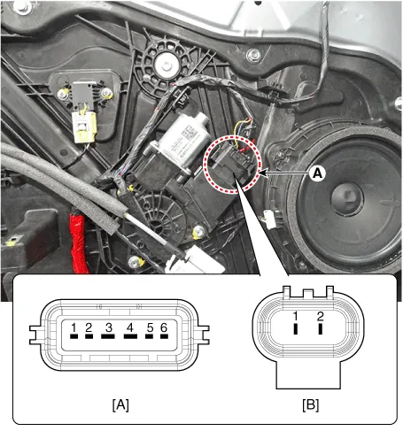
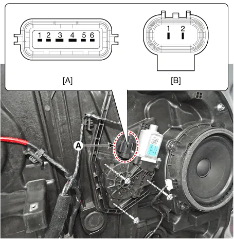
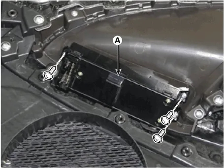
Disconnect the connector (A) from the motor.
(A : Safety, B : Standard)
|
| 4. |
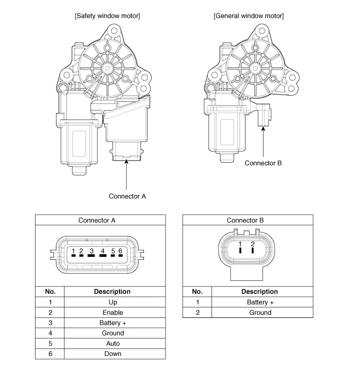
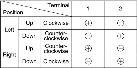
Connect the motor terminals directly to battery voltage (12V) and check
that the motor operates smoothly. Next, reverse the polarity and check
that the motor operates smoothly in the reverse direction. If the operation
is abnormal, replace the motor.
[Standard Window motor]
|
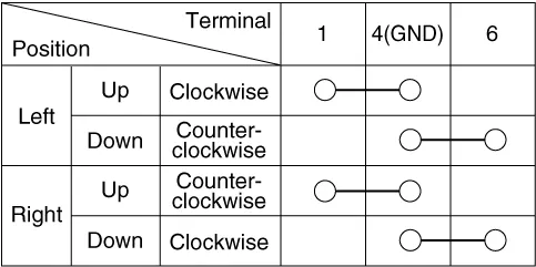
| 5. |
Connect the terminal No. 2 and No. 3 to battery voltage (12V) and check
that the motor operates smoothly when connecting the terminals below.
[Safety Window motor]
|
| 1. |
Disconnect the negative (-) battery terminal.
|
| 2. |
Remove the rear door trim.
(Refer to Body - "Rear Door Trim")
|
| 3. |
Disconnect the connector (A) from the motor.
(A : Safety, B : Standard)
|
| 4. |
Connect the motor terminals directly to battery voltage (12V) and check
that the motor operates smoothly. Next, reverse the polarity and check
that the motor operates smoothly in the reverse direction. If the operation
is abnormal, replace the motor.
[Standard Window motor]
|
| 5. |
Connect the terminal No. 2 and No. 3 to battery voltage (12V) and check
that the motor operates smoothly when connecting the terminals below.
[Safety Window motor]
|
Power Window Switch. Components and components location
| Components |
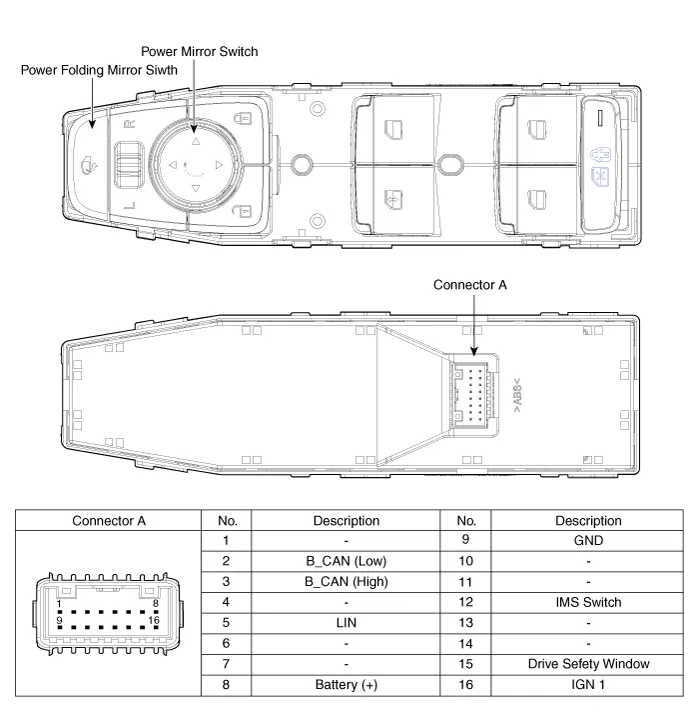
| [Driver Power Window Switch] |
| [Assist Power Window Switch] |
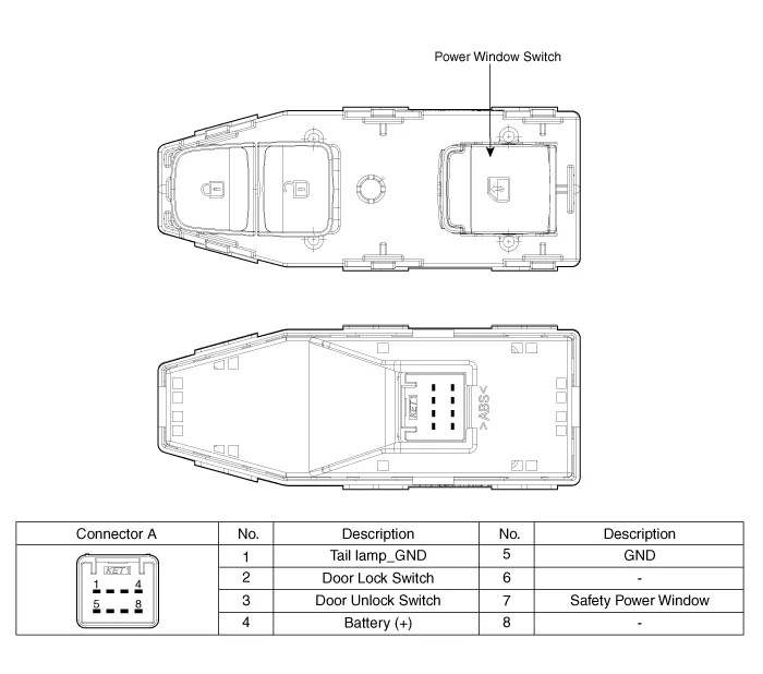
| [Rear Power Window Switch] |
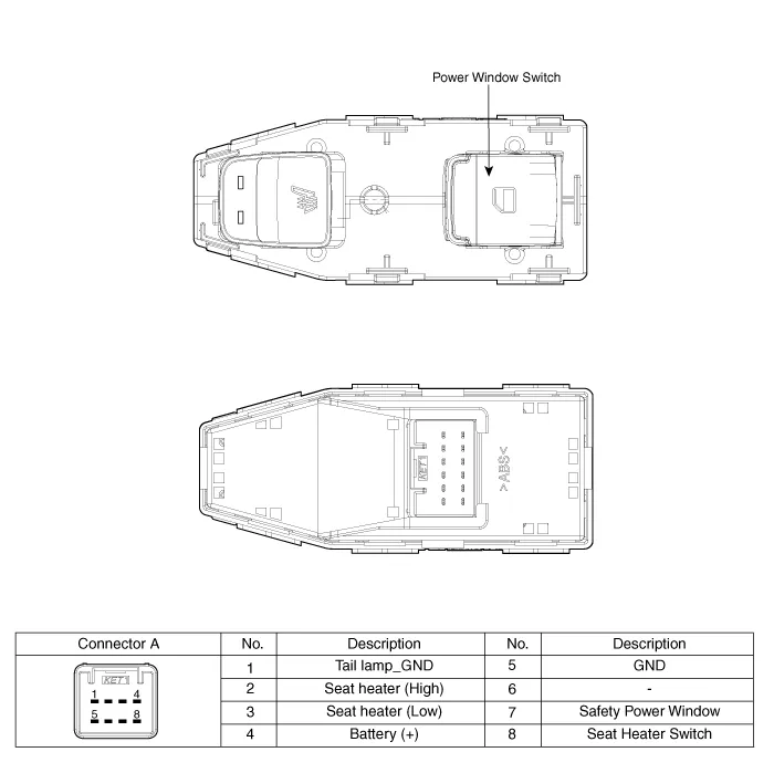
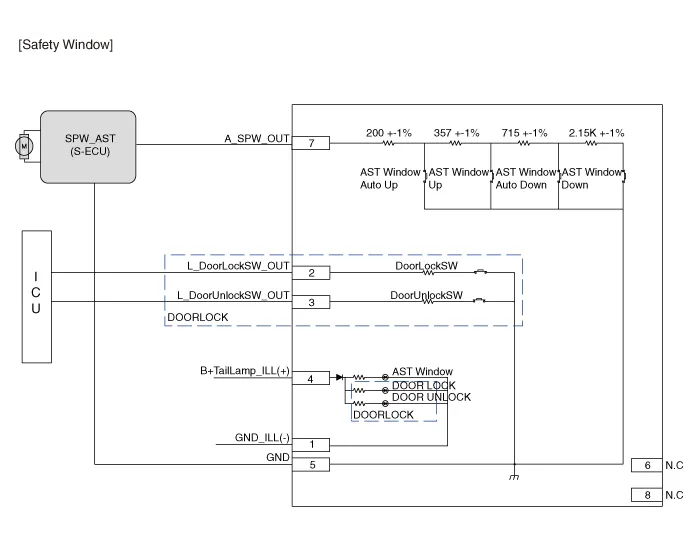
Power Window Switch. Schematic diagrams
| Circuit Diagram |

Power Window Switch. Repair procedures
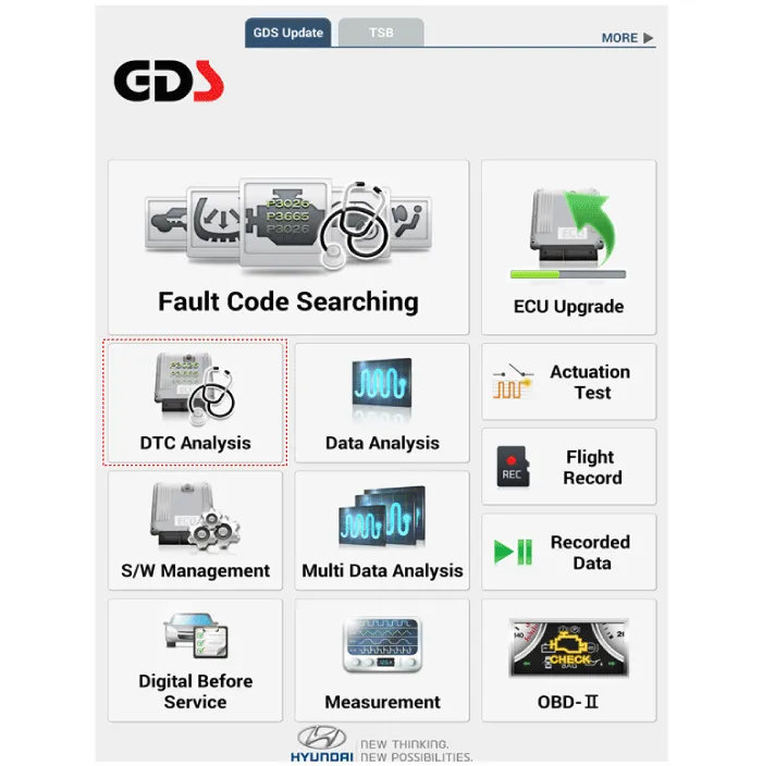
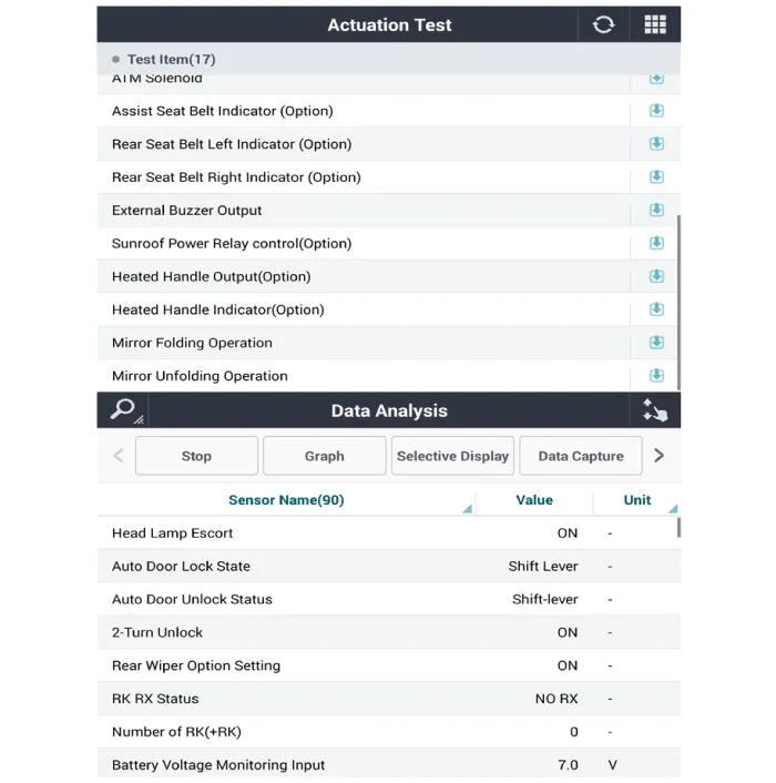
| Diagnosis with diagnostic tool |
| 1. |
In the body electrical system, failure can be quickly diagnosed by using
the vehicle diagnostic system (diagnostic tool).
The diagnostic system (diagnostic tool) provides the following information.
|
| 2. |
If diagnose the vehicle by diagnostic tool, select "DTC Analysis" and
"Vehicle".
|
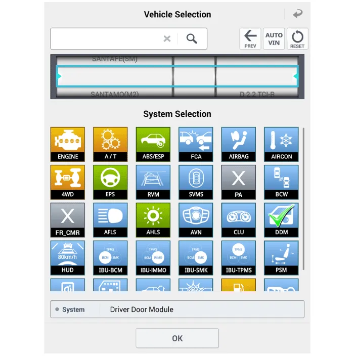
| 3. |
Select the 'Data Analysis' and 'Car model'.
|

| 4. |
Select the 'DDM' to search the current state of the input/output data.
|
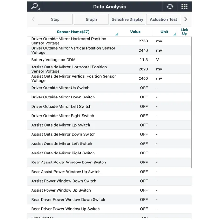
| 5. |
To forcibly actuate the input value of the module to be checked, select
option 'Actuation Test'.
|
| Removal |
| 1. |
Disconnect the negative (-) battery terminal.
|
| 2. |
Remove the front door trim.
(Refer to Body - "Front Door Trim")
|
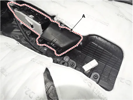
| 3. |
Remove the power window bezzel assembl (A) after loosening the mounting
screws.
|
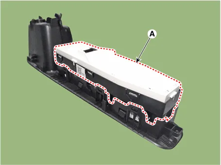
| 4. |
Remove the power window switch assembly (A) after loosening the mounting
screws.
|
| 1. |
Disconnect the negative (-) battery terminal.
|
| 2. |
Remove the front door trim.
(Refer to Body - "Front Door Trim")
|
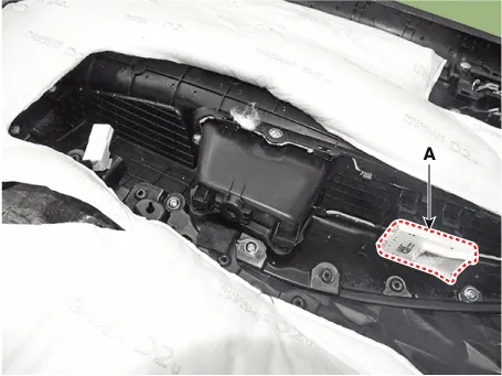
| 3. |
Remove the power window switch assembly (A) after loosening the mounting
screws.
|
| 1. |
Disconnect the negative (-) battery terminal.
|
| 2. |
Remove the rear door trim.
(Refer to Body - "Rear Door Trim")
|
| 3. |
Remove the power window switch assembly (A) after loosening the mounting
screws.
|
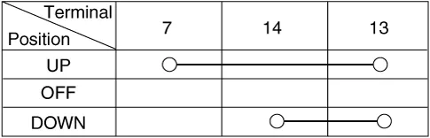
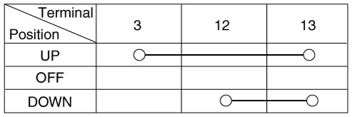
| 4. |
Check for continuity between the terminals in each switch position according
to the table. If the continuity condition is not normal, replace the
switch.
[Manual Window]
[Safety Window]
|
| Installation |
| 1. |
Install the power window switch assembly.
|
| 2. |
Install the front door trim after connecting the connector.
|
| 1. |
Install the power window switch assembly.
|
| 2. |
Install the front door trim after connecting the connector.
|
| 1. |
Install the power window switch assembly.
|
| 2. |
Install the rear door trim after connecting the connector.
|
Components and components location Component Location 1. Power door mirror 2. Power door mirror switch 3. Power folding mirror switch Power Door Mirror Switch.
Components and components location Component Location 1. Rear glass defogger relay (Buil-in engine room relay box) 2.
Other information:
Hyundai Santa Fe (TM) 2019-2023 Service and Repair Manual: Components and components location
Component Location Index Engine Room 1. Service port (High pressure) 2. A/C pressure transducer (APT) 3. Service port (Low pressure) 4. Compressor 5. Suction & Liquid pipe assembly 6. Expansion valve Interior 1.
Hyundai Santa Fe (TM) 2019-2023 Service and Repair Manual: Heater
Heater Unit. Components and components location Component Location 1. Heater Unit Assembly Components 1. Heater unit assembly 2. Heater NVH pad 3. Heater seal duct 4.
Categories
- Manuals Home
- Hyundai Santa Fe Owners Manual
- Hyundai Santa Fe Service Manual
- Automatic Transaxle Control System
- Rear Disc Brake. Repair procedures
- Front Radar Unit. Repair procedures
- New on site
- Most important about car
