Hyundai Santa Fe (TM): Suspension System / Front Suspension System
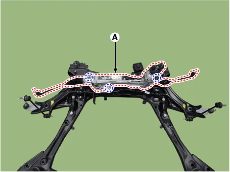
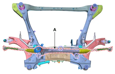
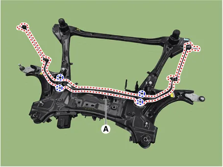
Components and components location
| Components Location |
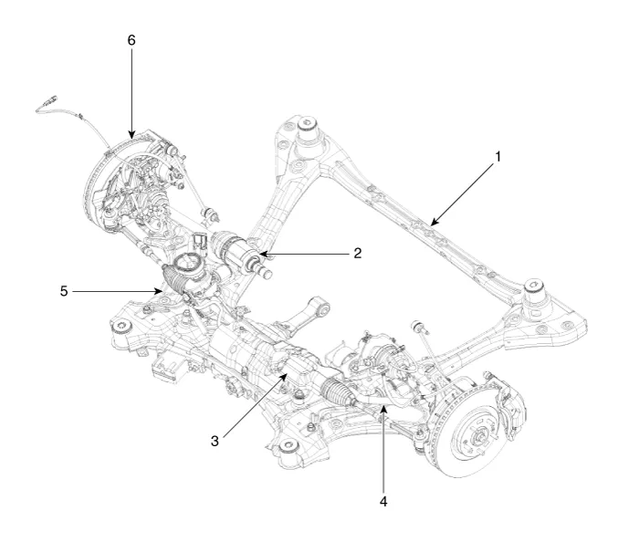
| 1. Front sub
frame 2. Drive shaft 3. Steering gear box |
4. Front stabilizer
bar 5. Front lower arm 6. Front knuckle assembly |
Front Strut Assembly. Components and components location
| Components |
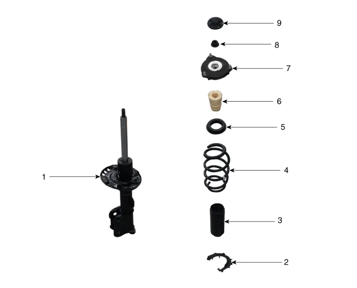
| 1. Strut assembly 2. Spring lower pad 3. Dust cover 4. Coil spring 5. Spring upper pad |
6. Bumper rubber 7. Insulator assembly & sturt bearing 8. Lock nut 9. Insulator cap |
Front Strut Assembly. Repair procedures
| Removal |
| 1. |
Loosen the wheel nuts slightly.
Raise the vehicle, and make sure it is securely supported.
|
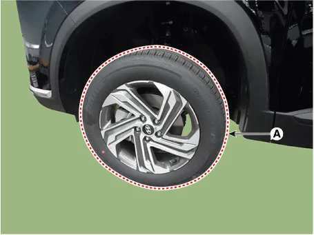
| 2. |
Remove the front wheel and tire (A) from the front hub.
|

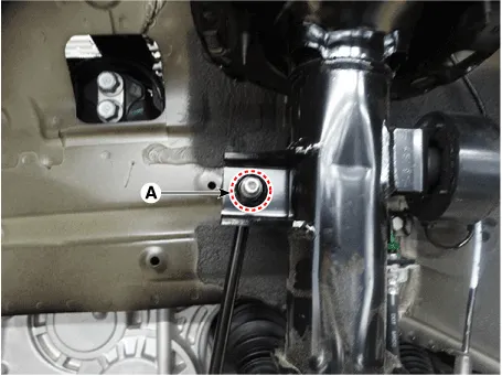
| 3. |
Disconnect the stabilizer link with the front strut assembly after loosening
the nut (A).
|
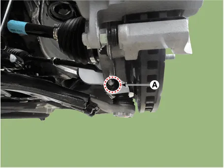
| 4. |
Loosen the mounting bolt (A) and then remove the brake hose bracket
from the strut assembly.
|

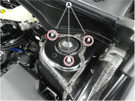
| 5. |
Loosen the upper strut mounting nuts (A).
|
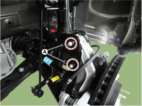
| 6. |
Remove the front strut assembly from the front axle by loosening the
bolts & nuts (A).
|
| Disassembly |
|

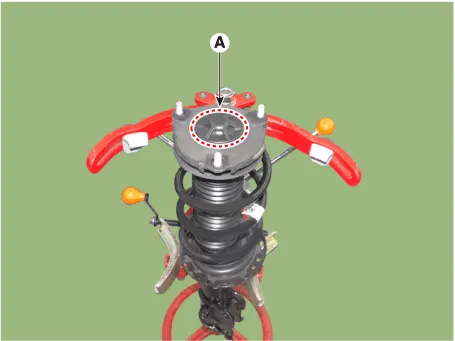
| 1. |
Remove the insulator cap (A).
|
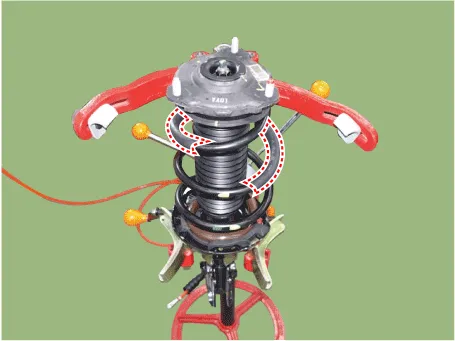
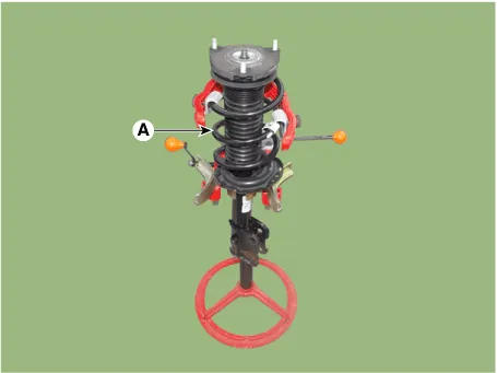
| 2. |
Using the spring compressor, compress the coil spring (A).
|
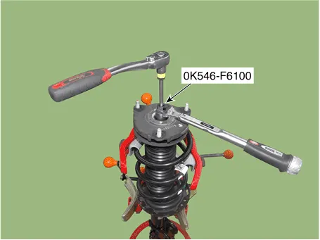
| 3. |
Using SST (0K546-F6100), loosen the self locking nut.
|
| 4. |
Remove the insulator, spring pad, coil spring and dust cover from the
strut assembly.
|
| Inspection |
| 1. |
Check the strut insulator for wear or damage.
|
| 2. |
Check rubber parts for damage or deterioration.
|
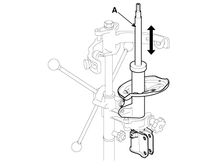
| 3. |
Compress and extend the piston rod (A) and check that there is no abnormal
resistance or unusual sound during operation.
|
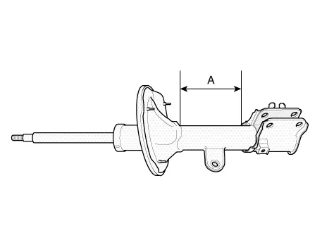
| 1. |
Fully extend the piston rod.
|
| 2. |
Drill a hole on the A section to remove gas from the cylinder.
|

| Reassembly |
| 1. |
Install the insulator, spring pad, coil spring and dust cover from the
strut assembly.
|
| 2. |
Compress and extend the piston rod (A) and check that there is no abnormal
resistance or unusual sound during operation
|
| 3. |
Using the special tool (0K546-F6100), install the self locking nut.
|
| Installation |
| 1. |
To install, reverse the removal procedures.
|
| 2. |
Check the alignment.
(Refer to Suspension System - "Alingment")
|
Front Lower Arm. Repair procedures
| Removal |
| 1. |
Loosen the wheel nuts slightly.
Raise the vehicle, and make sure it is securely supported.
|
| 2. |
Remove the front wheel and tire (A) from the front hub.
|
| 3. |
Remove the split pin and nut (A).
|
| 4. |
Remove the lower arm from the knuckle by using the SST (09568-4R100).
|
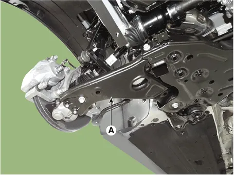
| 5. |
Remove the lower arm (A) from the sub frame after loosening the mounting
bolts.
|
| Inspection |
| 1. |
Check the bushing for wear and deterioration.
|
| 2. |
Check the lower arm for bending or breakage.
|
| 3. |
Check the lower arm for deformation.
|
| 4. |
Check the all bolts and nuts.
|
| Replacement |
| 1. |
Loosen the wheel nuts slightly.
Raise the vehicle, and make sure it is securely supported.
|
| 2. |
Remove the front wheel and tire (A) from the front hub.
|
| 3. |
Remove the split pin and nut (A).
|
| 4. |
Remove the lower arm from the knuckle by using the SST (09568-4R100).
|
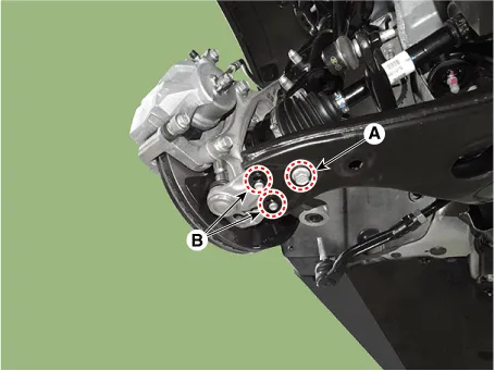
| 5. |
Remove the ball joint assembly after loosening the bolt (A) and nut
(B).
|
Front Stabilizer Bar. Repair procedures
| Removal |
| 1. |
Loosen the wheel nuts slightly.
Raise the vehicle, and make sure it is securely supported.
|
| 2. |
Remove the front wheel and tire (A) from the front hub.
|
| 3. |
Disconnect the stabilizer link with the front strut assembly after loosening
the nut (A).
|
| 4. |
Remove the split pin and nut (A).
|
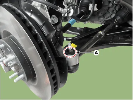
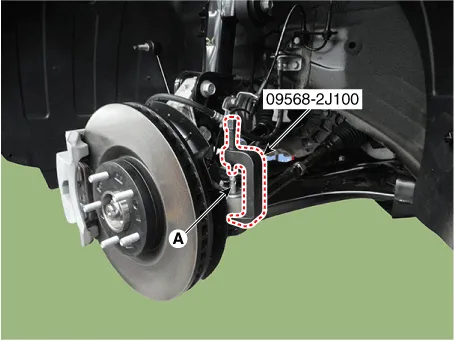
| 5. |
Remove the tie rod end ball joint (A) using the SST (09568-2J100).
|
| 6. |
Remove the split pin and nut (A).
|
| 7. |
Remove the lower arm from the knuckle by using the SST (09568-4R100).
|
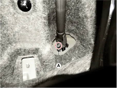
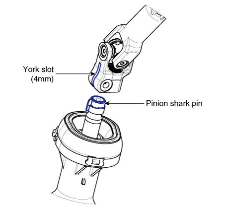
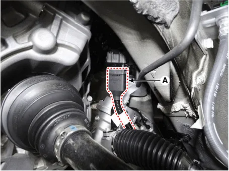
| 8. |
Loosen the bolt (A) and then disconnect the universal joint assembly
from the pinion of the steering gear box.
|
| 9. |
Remove the under cover.
(Refer to Engine Mechanical System - "Engine Room Under Cover")
|
| 10. |
Disconnect the R-MDPS main connector (A). [R-MDPS Type only]
|
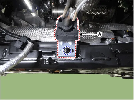
| 11. |
Remove the muffler rubber hanger (A) from the sub frame after loosening
the mounting bolt.
|
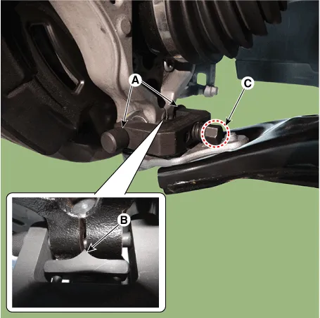
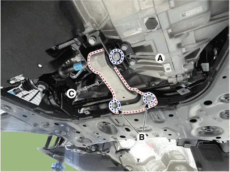
| 12. |
Remove the roll rod bracket (C) by loosening the bolt (A), (B).
|
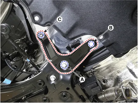
| 13. |
Remove the sub frame stay after loosening the mounting bolts (A, B)
and nut (C).
|
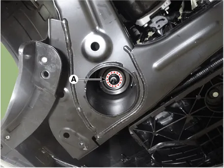
| 14. |
Loosen the sub frame mounting nuts (A).
|
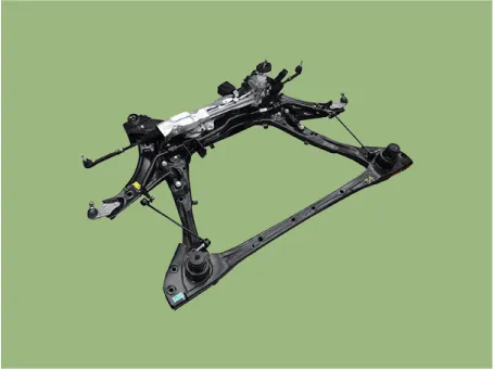
| 15. |
Remove the sub frame.
|
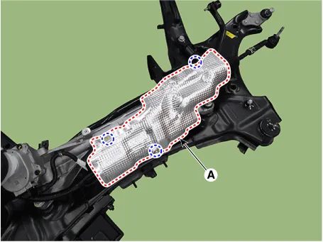
| 16. |
Remove the heat protector (A).
[R-MDPS]
[C-MDPS]
|
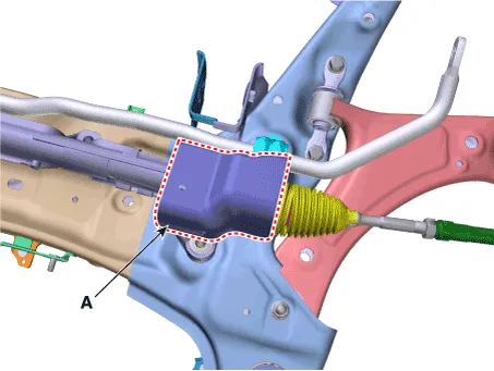
| 17. |
Remove the steering gearbox (A) from the front sub frame by loosening
the mounting bolts.
[R-MDPS]
[C-MDPS]
|
| 18. |
Remove the stabilizer bar (A) from the sub frame after loosening the
mounting bolts.
|
| Inspection |
| 1. |
Check the bushing for wear and deterioration.
|
| 2. |
Check the front stabilizer bar for deformation.
|
| 3. |
Check the front stabilizer link ball joint for damage.
|
| Installation |
| 1. |
Install in the reverse order of removal.
|
| 2. |
Check the alignment.
(Refer to Suspension System - "Alingment")
|
Sub Frame. Repair procedures
| Removal |
| 1. |
Loosen the wheel nuts slightly.
Raise the vehicle, and make sure it is securely supported.
|
| 2. |
Remove the front wheel and tire (A) from the front hub.
|
| 3. |
Disconnect the stabilizer link with the front strut assembly after loosening
the nut (A).
|
| 4. |
Remove the split pin and nut (A).
|
| 5. |
Remove the tie rod end ball joint (A) using the SST (09568-2J100).
|
| 6. |
Remove the split pin and nut (A).
|
| 7. |
Remove the lower arm from the knuckle by using the SST (09568-4R100).
|
| 8. |
Loosen the bolt (A) and then disconnect the universal joint assembly
from the pinion of the steering gear box.
|
| 9. |
Remove the under cover.
(Refer to Engine Mechanical System - "Engine Room Under Cover")
|
| 10. |
Disconnect the R-MDPS main connector (A). [R-MDPS Type only]
|
| 11. |
Remove the muffler rubber hanger (A) from the sub frame after loosening
the mounting bolt.
|
| 12. |
Remove the roll rod bracket (C) by loosening the bolt (A), (B).
|
| 13. |
Remove the sub frame stay after loosening the mounting bolts (A, B)
and nut (C).
|
| 14. |
Loosen the sub frame mounting nuts (A).
|
| 15. |
Remove the sub frame.
|
| 16. |
Remove the heat protector (A).
[R-MDPS]
[C-MDPS]
|
| 17. |
Remove the steering gearbox (A) from the front sub frame by loosening
the mounting bolts.
[R-MDPS]
[C-MDPS]
|
| 18. |
Remove the stabilizer bar (A) from the sub frame after loosening the
mounting bolts.
|
| Installation |
| 1. |
Install in the reverse order of removal.
|
| 2. |
Check the alignment.
(Refer to Suspension System - "Alingment")
|
Troubleshooting Symptom Possible cause Remedy Hard steering Improper front wheel alignment Correct Excessive turning resistance of lower arm ball joint Replace Low tire pressure Adjust No power assist Repair and replace Poor return of steering wheel to center Improper front wheel alignment Correct Poor or rough ride Improper front wheel alignment Correct Malfunctioning shock absorber Repair or replace Broken or worn stabilizer Replace Broken or worn coil spring Replace Worn lower arm bushing Replace the lower arm assembly Abnormal tire wear Improper front wheel alignment Correct Improper tire pressure Adjust Malfunctioning shock absorber Replace Wandering Improper front wheel alignment Correct Poor turning resistance of lower arm ball joint Repair Loose or worn lower arm bushing Retighten or replace Vehicle pulls to one side Improper front wheel alignment Correct Excessive turning resistance of lower arm ball joint Replace Broken or worn coil spring Replace Bent lower arm Repair Steering wheel shimmy Improper front wheel alignment Correct Poor turning resistance of lower arm ball joint Replace Broken or worn stabilizer Replace Worn lower arm bushing Replace Malfunctioning shock absorber Replace Broken or worn coil spring Replace Wheel and tire diagnosis Rapid wear at the center Rapid wear at both shoulders Wear at one shoulder • Center-tread down to fabric due to excessive over inflated tires • Lack of rotation • Excessive toe on drive wheels • Heavy acceleration on drive • Under-inflated tires • Worn suspension components • Excessive cornering speeds • Lack of rotation • Toe adjustment out of specification • Camber out of specification • Damaged strut • Damaged lower arm Partial wear Feathered edge Wear pattern • Caused by irregular burrs on brake drums • Toe adjustment out of specification • Damaged or worn tie rods • Damaged knuckle • Excessive toe on non-drive wheels • Lack of rotation
Components and components location Components [2WD] 1. Rear shock absorber 2. Rear lower arm 3. Rear stabilizer bar 4.
Other information:
Hyundai Santa Fe (TM) 2019-2023 Service and Repair Manual: General safety information and caution
General Safety Information and Caution 1. Be careful when driving the vehicle using the smart cruise control system as follows. (1) On curves or inclines/declines • The smart cruise control system may have limits
Hyundai Santa Fe (TM) 2019-2023 Service and Repair Manual: Driver Parking Assistance System
Desctiprion and operation Description ADAS_PRK is a unit that controls the functions required for ADAS parking. If the ADAS_PRK is applied, the parking distance warning function is also controlled by the ADAS_PRK. System Function Parking Collision-Avoidance Assist (PCA) PCA is a parking safety system
Categories
- Manuals Home
- Hyundai Santa Fe Owners Manual
- Hyundai Santa Fe Service Manual
- Rear seats
- LCD Display
- Lane Following Assist (LFA)
- New on site
- Most important about car
